
Subscribe to Our Youtube Channel
Related Manuals for Sonifex Redbox RB-SD1IP

Summary of Contents for Sonifex Redbox RB-SD1IP
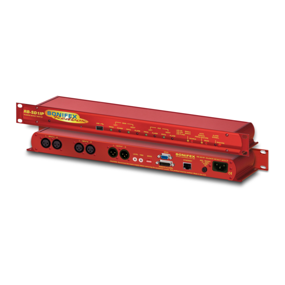
- Page 1 Redbox RB-SD1IP Silence Detection Unit With Ethernet & USB Manufacturers of audio & video products for radio & TV broadcasters...
- Page 2 Information in this document is subject to change without notice and does not represent a commitment on the part of the vendor. Sonifex Ltd shall not be liable for any loss or damage whatsoever arising from the use of information or any error contained in this manual.
-
Page 3: Table Of Contents
Fig 3-1: RB-SD1IP Front Panel GPI/O Connector Fig 4-1: Sonifex Service Discovery - Bonjour Page Ethernet Connector Fig 4-2: Sonifex Service Discovery - Legacy Discovery Page Front Panel Selectors and Indicators Fig 4-3: RB-SD1IP Screenshot of the Webserver Home Page Power Indicator... - Page 4 Warranty Registration Register Online for an Extended 2 Year Warranty As standard, Sonifex products are supplied with a 1 year back to base warranty. If you register the product online, you can increase your product warranty to 2 years and we can also keep you informed of any product design improvements or modifications.
-
Page 5: Product Warranty - 2 Year
Sonifex website within 30 days of purchase, you accordance with the provisions of this Contract. A reference to the consent, can increase your product warranty to 2 years. Go to the Sonifex website at: acknowledgement, authority or agreement of the Company means in http://www.sonifex.co.uk/technical/register/index.asp to apply for your 2... - Page 6 Warranty (vi) the defect has not arisen from a design made, furnished or At the request and expense of the Purchaser the Company will test specified by the Purchaser; the Goods to ascertain performance levels and provide a report of the results of that test.
-
Page 7: Unpacking Your Product
If you require a different power lead, please let us know when ordering the product. Repairs & Returns Please contact Sonifex or your supplier if you have any problems with your Sonifex product. Email technical.support@sonifex.co.uk for the repair/ upgrade/returns procedure, or for support & questions regarding the... - Page 8 T: +44 (0)1933 650 700 • F: +44 (0)1933 650 726 CE Declaration of Conformity and Approval Information This document certifies that the Sonifex product that you have purchased is compliant with CE specifications. If you would like further information on...
-
Page 9: Safety & Installation Of Mains Operated Equipment
Safety & Installation Safety & Installation of Mains Power Cable & Connection Operated Equipment An IEC power connector is supplied with the product which has a moulded plug attached – this is a legal requirement The mains lead is automatically There are no user serviceable parts inside the equipment. -
Page 10: Weee Directive
All products manufactured by Sonifex Ltd have the WEEE directive label Atmosphere placed on the case. Sonifex Ltd will be happy to give you information about local organisations that can reprocess the product when it reaches its “end The units should be installed in an area that is not subject to excessive of use”, or alternatively all products that have reached “end of use”... -
Page 11: Rb-Sd1Ip Silence Detection Unit
The RB-SD1IP Silence detection unit is an upgraded version of the existing SNMP V1 is implemented so that the unit can be monitored by existing Sonifex RB-SD1. The unit is a 1U rack mount device used to monitor an Network Management Systems (NMS). The addition of 6 extra GPI pins to unattended stereo studio feed and in the event of the signal going “quiet”... - Page 12 Introduction The unit has 2 operational modes for restoring a signal - automatic or The RB-SD1IP has been designed to have a passive signal path through the manual. In both modes the unit will automatically switch over to a valid main input, so if power to the unit fails, the signal input will still be routed auxiliary source upon detecting silence.
-
Page 13: System Block Diagram
System Diagram System Block Diagram Left Stereo Input A Right Left Stereo Input B 9 Way Right GPI Socket Stereo Outputs Consumer Gain Select Left Ethernet USB Audio Balanced Reset Microprocessor Right Output Select 0-9D-F Level Remote Relay Control Select 0-9D-F Time Select... -
Page 14: Rear Panel Connections And Operation
Rear Panel Connections and Operation Rear Panel Connections and Operation Stereo GPI/O A Inputs B Inputs Outputs Mode Socket Level Time Remote Ethernet Fuse Control Control Plug Power Inlet Fig 2-1: RB-SD1IP Rear Panel Switch A/B Inputs (Left and Right) Level dBu -60 -57 -54 -51 -48 -45 -42 -39 -36 -33 -30 -27 -24 -21 -18 -15 There are four XLR-3 inputs, two for channel A (Left &... -
Page 15: Remote Alarms Connector
Rear Panel Connections and Operation 1. Stereo/Mono Switch – The configuration of this defines whether you 4. Switch/No Switching in Alarm State – This defines whether the unit want to switch sources when left and/or right channel of the incoming switches to the auxiliary input upon silence detection. -
Page 16: Gpi/O Connector
Rear Panel Connections and Operation GPI/O Connector Pin 13 Relay 2 Common I/O N/O to Pin 6, N/C to Pin 5 There are 6 GPI pins available on a 9 way female D-type connector located Pin 14 Max Time Whilst Latched Active Low make to Pin 1 above the Remote Alarms Connector. -
Page 17: Front Panel Selectors And Indicators
Front Panel Selectors and Indicators Front Panel Selectors and Indicators Source Select Restore Button Power Reset Main Switch and and Alarm Button Socket Indicators Indicators Indicator Indicator Auto/Manual Mode Switch and Indicator Fig 3-1: RB-SD1IP Front Panel Power Indicator For example: A single red LED confirms the presence of an active power supply to the Track_05.wav unit. -
Page 18: Main And Aux Indicators
Front Panel Selectors and Indicators Source Select and Indicator device contains files at a sample rate of 24 kHz, set the default sample rate to 48 kHz range, which also supports the subfrequencies 12kHz & 24kHz, to The preferred Main input source is selectable via a recessed push button switch on the front panel, or it can be controlled remotely (pin 10) and from ensure the unit always boots up ready to play at the correct clock frequency. -
Page 19: Restore Alarm Indicator
Front Panel Selectors and Indicators Reset to Defaults Description It is possible to reset the unit to default configuration settings, including LED On Automatic Mode – During an alarm condition when the network settings, from the front panel. To perform a full reset you must main source returns, it is switched back automatically, press and hold the Restore button whilst resetting or power cycling the although a valid signal must persist for at least the... -
Page 20: Rb-Sd1Ip Network Discovery And Webserver
Ensure that the PC has dynamic addressing enabled and you will be changed to make it more memorable or descriptive of an implementation, able to use the Sonifex discovery application on this mini network to access however, conflicting names should be avoided. -
Page 21: Sonifex Service Discovery App
The application also offers legacy sonifex.co.uk/technical/software). This application uses Bonjour to locate discovery for systems which do not support Bonjour or for Sonifex hardware networked hardware and discover what services it has to offer. On a device which is not running MDNS-SD. -
Page 22: Home Page
Each page follows the same standard layout as the Home override has been activated by the remote connector page, with current status/configuration settings on the left and tooltip explanations in the box on or the SNMP interface. the right. The page footer contains contact details for Sonifex Ltd. -
Page 23: Device Information
Network Discovery and Webserver Device Information This page shows general information about the connected RB-SD1IP. Fig 4-4: RB-SD1IP Screenshot of the Webserver Device Page... -
Page 24: Network Settings
Network Discovery and Webserver Network Settings Host Name The Host Name for this unit is used for Multicast DNS Service Discovery. The default Host Name is the unit Hardware Type, appended with the unique Serial Number. IP Address Please enter the static IP Address that you wish to assign to this unit. -
Page 25: Configuration : Level & Time Settings
Network Discovery and Webserver Silence Level Select the desired audio level to be treated as silence. Silence Time Enter the desired length of time for which the signal must be below the selected Silence Level, before an alarm is triggered. (Format; Hrs : Mins : Secs) Restore Time Enter the desired length of time for which a signal above the selected Silence Level must persist, before... -
Page 26: Configuration : Source Settings
Network Discovery and Webserver Source Indication Choose the status that you wish the front panel Source LED and the remote Source Select pin to indicate. Main Selection - indicates which input is currently selected as the Main source. Output Signal - indicates which input is currently being routed to the output, active for A, inactive for B and flashing for USB. -
Page 27: Configuration : Alarm Settings
Network Discovery and Webserver Configuration : Alarm Settings Channel Mode Control how alarm signals are handled with regard to audio switching: Stereo - both Main channels are required, the unit will attempt to switch sources if either falls silent. Mono - only one Main channel is required, the unit will only attempt to switch to Auxiliary if both Main channels fall silent. -
Page 28: Configuration : Snmp Settings
Network Discovery and Webserver Configuration : SNMP Settings This page allows you to configure the SNMP community string and SNMP Trap destinations. The traps themselves are enabled on the relative webpages, for example GPI and Levels & Times. Community String The Community String may be up to 20 characters long. -
Page 29: Configuration : Usb Settings
Network Discovery and Webserver Default Rate We recommend that a USB device is loaded with files which are all in the same sample frequency range (e.g. 48 kHz, 24 kHz and 12 kHz), this will avoid any detection or playback delays between tracks as the internal clock is adjusted for different sample rates. -
Page 30: Configuration : Remote Settings
Network Discovery and Webserver Configuration : Remote Settings This page allows you to configure how you would like the pins on the rear panel, 15 way, remote connector to behave. Remote Controls This allows you to Lock or Unlock Pins 5, 7, 10 and 14. -
Page 31: Configuration : Gpio Settings
Network Discovery and Webserver Configuration : GPIO Settings This page allows you to set up and configure the 6 General Purpose Inputs (GPI) on the rear panel, 9 way port. Select the GPI that you wish to configure from the drop down list. You can configure all 6 of the pins before hitting submit. -
Page 32: Configuration : Physical Settings
Network Discovery and Webserver Configuration This option allows you to select whether to use the options set by the physical controls on the unit, or the options set up using this webserver. When using the physical control settings many options on the webpage will become grey to indicate that they are not currently enforced. -
Page 33: Update
Network Discovery and Webserver Update The current firmware version on this unit is shown at the top of the page. To find out if there is new firmware for your unit, check our website. If an update is available, download the latest file from our website in the “.dwn”... -
Page 34: Technical Specification Rb-Sd1Ip
Technical Specification Technical Specification RB-SD1IP Silence Switch Defeat: Disable/enable silence switching, via DIP Audio Specification switch or GUI Maximum Input Level: +28dBu Remote Start: Latched or momentary, via DIP switch or GUI Input Impedance: Ethernet: 10/100Mbps on 1xRJ45 socket with status LEDs Maximum Output Level: +28dBu Mains Input:... - Page 35 Technical Specification Equipment Type RB-SD1IP Redbox Silence Detection unit with Ethernet & USB Physical Specification Dimensions (Raw): 48cm (W) x 10.8cm (D) x 4.2cm (H) (1U) 19” (W) x 4.3” (D) x 1.7” (H) (1U) Dimensions (Boxed): 58.5cm (W) x 22.5cm (D) x 7cm (H) 23”...
- Page 36 . s o n i f e x . c o . u k t:+44 (0)1933 650 700 f:+44 (0)1933 650 726 sales@sonifex.co.uk...
Need help?
Do you have a question about the Redbox RB-SD1IP and is the answer not in the manual?
Questions and answers