
Summary of Contents for Smarteh LPC-2.C05
- Page 1 USER MANUAL Longo programmable controller LPC-2.C05 GSM module Version 5 SMARTEH d.o.o. / Poljubinj 114 / 5220 Tolmin / Slovenia / Tel.: +386(0) 388 44 00 / e-mail: info@smarteh.si / www.smarteh.si...
- Page 2 Longo programmable controller LPC-2.C05 Written by SMARTEH d.o.o. Copyright © 2012, SMARTEH d.o.o. User Manual Document Version: 005 July 1, 2012...
- Page 3 24 months is valid from the date of sale to the end buyer, but not more than 36 months after delivery from Smarteh. In case of claims within warranty time, which are based on material malfunctions the producer offers free replacement. The method of return of malfunctioned module, together with description, can be arranged with our authorized representative.
-
Page 4: Table Of Contents
Longo programmable controller LPC-2.C05 Longo programmable controller LPC-2.C05 1 DESCRIPTION...................1 2 FEATURES..................2 3 INSTALLATION..................3 3.1 Connection scheme..............3 3.2 Mounting instructions..............5 3.3 Module labeling................7 4 TECHNICAL SPECIFICATIONS..............8 APPENDIX A: PROGRAMMERS GUIDE............9 5 CHANGES ..................11 6 NOTES..................12... -
Page 5: Description
“+” symbol (e.g. Slovenian international code is 00386). When LPC-2.C05 module is correctly installed and it is ready to operate. In this case status LED1 must blink (refer to the Table 6). The starting sequence is executed once after reset. Complete time base is 40 sec (see below). -
Page 6: Features
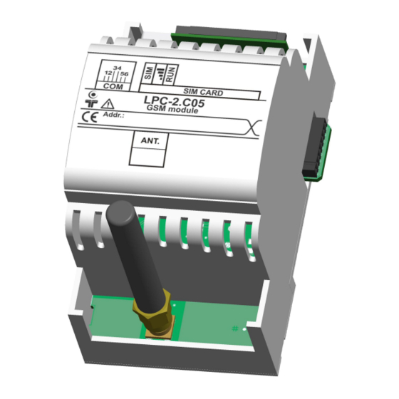
Longo programmable controller LPC-2.C05 2 FEATURES Figure 1: LPC-2.C05 communication module. Table 1: Technical data Dual band 900/1800 MHz Optional RS-232 communication port, 9600 bps, 8 bits, one stop bit, no parity, no flow control, reserved for external AT command... -
Page 7: Installation
Longo programmable controller LPC-2.C05 3 INSTALLATION 3.1 Connection scheme Figure 2: Connection scheme Table 2: ANT. ANT. Antenna connector SMA/F (GSM antenna SMA/M) Table 3: SIM CARD SIM CARD SIM card connector Table 4: K1 Internal BUS Data & DC power supply... - Page 8 Longo programmable controller LPC-2.C05 Table 6: LEDs OFF: power off Green LED: indicates C05 SIM Blink once: SIM card not inserted state or PIN enabled ON: SIM status OK OFF: power off Green LED: indicates C05 Network Blink once & ON: Low GSM signal...
-
Page 9: Mounting Instructions
Mounting instructions: 1. Switch OFF main power supply. 2. Mount LPC-2.C05 module to the provided place inside an electrical panel (DIN EN50022-35 rail mounting). 3. Screw antenna (delivered together with LPC-2.C05 module) to the antenna connector. -
Page 10: Module Labeling
Label 2 description: 1. S/N:MC3-S9-0500000190 is the serial number. MC3 – short product name, • S9 – user code (test procedure, e.g. Smarteh person xxx), • 0500000190 – year and current stack code, • 05 – year (last two cyphers), •... -
Page 11: Technical Specifications
Longo programmable controller LPC-2.C05 4 TECHNICAL SPECIFICATIONS Table 7: Technical specifications Power supply from internal BUS Power consumption Optional RS-232 communication port, 9600 bps, 8 Communication bits, one stop bit, no parity, no flow control, reserved for external AT commands... -
Page 12: Appendix A: Programmers Guide
Longo programmable controller LPC-2.C05 APPENDIX A: PROGRAMMERS GUIDE Memory allocation Tables below shows the example of memory allocation for C05 on position #1. Boolean variables Rx: I/O Module FBOOL8 I/O Name BIT0 BIT1 BIT2 BIT3 BIT4 BIT5 BIT6 BIT7 Range 0 .. - Page 13 Longo programmable controller LPC-2.C05 Word variables Rx: I/O Module FWORD16 I/O Name WORD1 WORD2 WORD3 WORD4 WORD5 WORD6 WORD7 WORD8 Range 0 .. 65535 MC3: 0x160a + (N * 0x0040) Address MC7: 0x0703 + (N * 0x0040) Word variables Tx:...
-
Page 14: Changes
Longo programmable controller LPC-2.C05 5 CHANGES The following table describes all the changes to the document. Date Description 1.7.2012 CGP General update , New HW and FW version 11.5.2010 Updated warranty permanence. 30.6.2005 The initial version, issued as LPC-2.C05 module UserManual. -
Page 15: Notes
Longo programmable controller LPC-2.C05 6 NOTES...
Need help?
Do you have a question about the LPC-2.C05 and is the answer not in the manual?
Questions and answers