Table of Contents
Advertisement
Quick Links
Advertisement
Table of Contents

Summary of Contents for Foss OMC-W36
- Page 1 OMC-W36 CONNECTOR HEAT OVEN USER´S MANUAL Issued: March, 2018 Foss Fibre Optics, s.r.o. Odnorarska 52 831 02, Bratislava Slovak republic Phone: +421 2 48205200 Fax: +421 2 48205231 E-mail: office.sk@fossfibreoptics.com Web: www.fossfibreoptics.com...
- Page 2 Blank page...
- Page 3 OMC-W36 CONNECTOR HEAT OVEN USER´S MANUAL Copyright © 2000, Optocon technologies s.r.o. All rights reserved. This document was prepared for use by customers, licensees and personnel. All the information contained in this manual is the property of Optocon technologies s.r.o. and shall not be reproduced whole or in part, without prior written approval.
- Page 4 PLEASE OBSERVE THE FOLLOWING INSTRUCTIONS: WARNING • NEVER touch or put your hands or fingers on the ferrule/plug cassette block while the heating process has been started or interrupted. Actual temperature of the ferrule cassette is indicated on the LCD display. Touching the hot ferrule/plug cassette may result in serious injury.
- Page 5 • NEVER perform any of the following. Doing so may lead to fire, electrocution or other serious accident: hit or subject the unit to any kind of shock place the unit on an unsteady surface forcibly bend and place heavy objects on the unit cover the unit while in operation with any kind of cover disabling proper natural ventilating...
- Page 6 Blank page...
-
Page 7: Table Of Contents
CONTENTS CHAPTER 1 1.1 Introduction 1.2 Standard packing items 1.3 Heat oven description, names and functions of the parts CHAPTER 2 2.1 Installation place and environmental conditions 2.2 Power supply 2.3 Specifications 2.4 Installation CHAPTER 3 3.1 Software description 3.2 Operating the unit 3.2.1 Setup procedure 3.2.2 Process confirmation 3.2.3 Running the heating process... -
Page 8: Introduction
CHAPTER 1 1.1 Introduction OMC-W36 is a user programmable heat oven with a vertical tray used for hardening the epoxies used during the assembly of fiber optic connectors. It is primary intended to heat the fiber optic ferrules and plug type fiber optic connectors in which the epoxies bond the optical fiber. -
Page 9: Standard Packing Items
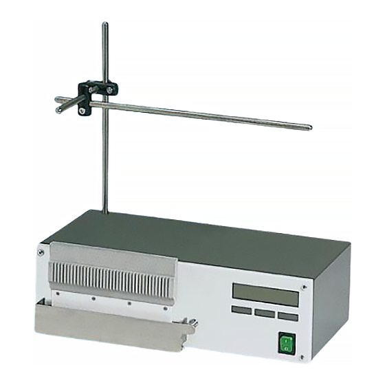
OMC-W36 is recommended for curing the following types of fiber optic ferrules/connectors: standard 2.5 mm ceramic, glass and metal singlemode or multimode ferrules standard 1.25 mm ceramic, glass and metal singlemode or multimode ferrules standard plug type fiber optic connectors with 2.5 mm ferrules (FC, SC, ST, E2000, DIN, etc.) - Page 10 The main unit houses all crucial electrical and electronic components that are necessary for proper function of the unit. Front and back view of the main unit with names of each part of main unit is shown on figure 1.3.1. Vertical Tray Heating plate LCD display...
- Page 11 Clamps Stop ring Steel bars Figure 1.3.2. Assembled cord holder The cassette is the holding device for the connector components, which have to be heated. The groove plate is a part of the cassette, though it can be removed and replaced by different types of groove plates.
-
Page 12: Installation Place And Environmental Conditions
Do not install the oven in places that are near an air conditioning vent. 2.2 Power supply The power supply conditions for the OMC-W36 heat oven are as follows: Model OMC-W36-1: • Power supply voltage ....single phase AC 110V ± 10% •... -
Page 13: Specifications
Model OMC-W36-2: • Power supply voltage ....single phase AC 230V ± 10% • Power supply frequency ....50 Hz ± 10% • Power consumption rating ... 250W 2.3 Specifications Operating temperature range: 40 °C – 140 °C Temperature stability +/- 2 °C WARNING •... - Page 14 Check the heat oven at the end of installation by the following procedure: Power on the unit with the power switch on the front panel of the unit. Confirm that the power switch and LCD display is lit. The following message should appear on the LCD (fig.
-
Page 15: Software Description
CHAPTER 3 3.1 Software description The software allows the user to have full control over the heating process. It allows setting up cure temperature and cure time, these are necessary parameters dependent on the kind of epoxy. All the information that is necessary to the operator is shown on the LCD display on the front panel. -
Page 16: Operating The Unit
3.2 OPERATING THE UNIT Before starting the heating process, make sure that you performed the correct installation steps, as described in Chapter 2. Turn on the unit and the message HEAT OVEN READY shall appear on the LCD display, fig. 3.2.1. HEAT OVEN READY SETUP NEXT... -
Page 17: Process Confirmation
procedure again. Right after pressing the OK button, cure time setup procedure follows, fig. 3.2.1.2. CURE TIME 15MIN UP button OK button DOWN DOWN button Figure 3.2.1.2 Setup process for the cure time parameter Set the desired cure time by pressing the UP or DOWN button, then confirm by pressing the OK button once. - Page 18 Once the RUN button has been pressed, the heating process will start, as described in paragraph 1.1, chapter 1. The heating process consists of three subsequent periods: the heating period, curing period and cool-down period. So, first heating period starts, fig. 3.2.3.1 - Heating period HEATING 045°C...
-
Page 19: Interrupting The Heating Process
- Cool down period FINISHED 118°C SETUP button AGAIN button SETUP AGAIN Figure 3.2.3.3. Display contents during the cool down period Cool down period starts right after finishing the curing period. The contents of the LCD display are shown on fig. 3.2.3.3 . - Page 20 It is strongly The actual temperature of the cassette is shown on the LCD. recommended not to remove the cassette from the tray until the temperature decreases to 50°C or less . If removing the cassette is unavoidable due to specific reasons (epoxy leak, fiber has broken, etc.), the operator must arrange that there is no risk of other persons getting too close to the hot cassette and thus avoid accidental contact.
-
Page 21: Troubleshooting
CHAPTER 4 4.1 Troubleshooting This chapter explains how to solve various problems when they arise. If the problem is not fixed by taking the action indicated, contact your salesperson at your earliest convenience. Problem description Possible cause Action No power Power cable is loose or Plug in the power cord damaged... -
Page 22: Changing The Fuse
4.2 Changing the fuse If the fuse blows, use the following procedure to change it. WARNING • Always turn the power off and unplug the power cord from the socket before changing the fuse. Failure to do so may cause electrocution. Pull out the fuse box from the inlet on back panel.
Need help?
Do you have a question about the OMC-W36 and is the answer not in the manual?
Questions and answers