
Related Manuals for Raveon RV-M3-M


Summary of Contents for Raveon RV-M3-M
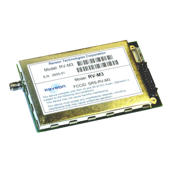
- Page 1 Model: RV-M3-M MURS Radio Modem Module Version D4 November, 2006 Raveon Technologies Corporation 2780 La Mirada Dr. Suite C Vista, CA 92081 www.raveontech.com...
- Page 2 The sophisticated over-the-air protocol hides the idiosyncrasies of RF communications from the user application. Raveon’s MURS radio modem’s 32-bit microprocessor handles all of the typical radio communication issues such as PLL loading, TX-RX timing, PA ramping, packetizing data, sending pre-ambles, synchronizing to receive data, and CRC checking.
- Page 3 Features • Built-in radio transceiver with integrated modem • Small size module. Perfect for hand-held OEM devices. • Lowest cost narrow-band radio modem • 16 bit ID and 16 bit address mask in each modem • Built-in CRC checking of the data. No bad data and no dribble bytes will come out. •...
-
Page 4: Specifications
Specifications General All measurements made per TIA-603-B Size (inches) ....................2.11 X 3.40 X 0.6 Vpwr input Voltage ......................5-8V DC Average current draw, unit off..................<250uA Average current draw, normal operation, receiving ............<60mA SLEEP mode (SLEEP pin grounded) current draw ............<25mA Current draw when transmitting data ..............<0.6A at 1/2W Power supply ripple and noise limit................. -
Page 5: User I/O Connector
User I/O Connector The User I/O is via a female 16-pin .100” header connector. The following pins are defined. Front-view of 16-pin header connector on modem module Pin # Name Function 5.1.1.1.1 Level / Specification User may supply the main DC power to the 1, 2 Power In/out... - Page 6 Serial Port Data and Handshaking In computer terminology, the RF modem is considered a “Data Communications Equipment” device, or DCE. The user’s hardware that the modem is connected to is considered “Data Terminal Equipment”, or DTE. Following is a description of how data and control is communicated over the various serial port signals between the modem (DCE) and another device (DTE) that the modem’s I/O port is connected to.
-
Page 7: User Serial Port Commands
User Serial Port Commands Overview The asynchronous serial portion the MURS RF modem is used to send and receive data over the air, as well as to configure the RF modem. In normal operation, the user sends data into the TxD pin of the user port, and this data will be sent over the air. -
Page 8: Configuration Mode Commands
Receive Frequency – Program the receive frequency for this See product data sheet. For MURS channel. Enter in Hz or MHz. The frequency will automatically data sheet. products, frequency be saved in non-volatile memory (flash) for this current channel cannot be changed. Company Confidential Raveon Technologies Corp. - Page 9 Used to set the radio on the center of the radio 12** +500 channel. Modulation Balance. Range: 0-100 88** Select RF CD output threshold – This value is the RSSI Range : 0-999 300** threshold where the carrier detect is asserted. Note: To force Company Confidential Raveon Technologies Corp.
- Page 10 Enable Remote Access – When enabled (set to a 0), the 0= Remote Access on modem will respond to over-the-air RPR requests and over-the- 1=Remote Access off air commands. Default is ON (0). See FireLine System Protocol Manual for remote diagnostics information. Company Confidential Raveon Technologies Corp.
-
Page 11: Packet Counter
Packet Mode is the factory-default operating mode. It is the easiest and most reliable mode of operation for a modem. Note: The configuration of the Radio Modem is done when it is in the “Command Mode”. Refer to Section Company Confidential Raveon Technologies Corp. - Page 12 User applications must (and often do), take this into account, and thus can operate with weaker signals and have longer communication range. Company Confidential Raveon Technologies Corp.
- Page 13 From the factory, the modems are configured and shipped ready-to-use. Out of the box, they will communicate on the default radio channel using the factory defaults. In general, the parameters you may want to modify will be: Company Confidential Raveon Technologies Corp.
-
Page 14: Programming Channels And Frequencies
ATSV (Save to non-volatile memory) command. Due to the nature of the synthesizer used in the radio, the frequency programmed into the unit must be an even multiple of its internal reference Company Confidential Raveon Technologies Corp. -
Page 15: Data Transmission
The over-the-air packet size may be set with the ATTT xx command. Once the modem receives one full packet of data via the serial port, it will automatically key the transmitter and send the data. Factory default is 80 bytes. Company Confidential Raveon Technologies Corp. -
Page 16: Busy Channel Lockout
Every modem has a Unit Address programmed into it, as well as the ID of the unit it will send data to. The Unit Address is programmed with the ATMY xxxx command, and the Unit Address of the destination modem (the Destination Address) is configured with the ATDT xxxx command. Company Confidential Raveon Technologies Corp. - Page 17 0000 mask will receive them also. Most users who do not use individual modem addressing, choose to set a global system address, and have all modems in their system use the same Unit ID and same destination address. Company Confidential Raveon Technologies Corp.
- Page 18 Mask. The result is the Effective Unit Address. The Effective Unit Address is compared to the Effective Destination Address, and if the two are identical, the data will be received. Note: Logically 1 = 1, 0 = 0, 0 = 0, 1 = 0 Company Confidential Raveon Technologies Corp.
- Page 19 FFFF requires that all digits in the address match. . Example 3 (able to receive a data from a group, 1230 – 123F) Sending to Destination Address = 1236 Receiving modem Unit Address = 1234 Receiving modem Address Mask = FFF0 Company Confidential Raveon Technologies Corp.
-
Page 20: Error Correction
ACK) is up to the user, but a number of 5 is usually a good compromise. If after 5 times, the data does not get through, then there probably is something seriously wrong with the channel or system. Company Confidential Raveon Technologies Corp. -
Page 21: Streaming Mode Operation
It will automatically de-key when there is no more data to send. Figure 3 illustrates the difference between the Packet Mode and the Streaming Mode of operation. Company Confidential Raveon Technologies Corp. -
Page 22: Baud Rate Selection
ATBD command. If the serial port baud-rate is slower than the over-the-air rate, an internal buffer in the modem will hold the data as it is sent out the serial port. Company Confidential Raveon Technologies Corp. -
Page 23: Bit Errors
CTS signal on the DB-9 serial connector. When CTS is negated, the internal buffers are more than 80% full. When it is asserted and it is “Clear to Send”, the buffers are less than 80% full. Company Confidential Raveon Technologies Corp. -
Page 24: Tune-Up And Alignment
Use the ATR0 command to read or set the value. This value is negative, and is typically around - 200. 11.3 TX Modulation Balance 1. Transmit random data using the ATTD 1 command. Company Confidential Raveon Technologies Corp. -
Page 25: Diagnostic Provisions
Low-level internal statistics – Returns various low-level statistics. STAT 2 statistics These are subject to change in various firmware revisions. screen Compile date and time – Returns the data and the time that the STAT 3 Date and time firmware was compiled. Company Confidential Raveon Technologies Corp. - Page 26 Run time Run Time – Returns the amount of time that the modem has been STAT 4 display powered up and running. screen Company Confidential Raveon Technologies Corp.
- Page 27 (speed of the main Operating System, in Hz. Typical 8000-30000. OS Speed (the DAC value that biases the VCO in the radio. 0-1024 = 0-3.3V) VCO Bias hhhh (hexadecimal representation of an internal configuration word.) Config Company Confidential Raveon Technologies Corp.
- Page 28 ATVR The firmware version in the modem ATDT The ID the modem is programmed to send data to. ATVB DC voltage, in millivolts of the DC input to the modem. UPTIME Number of seconds since this modem has turned on. Company Confidential Raveon Technologies Corp.
- Page 29 ATMA command. This allows the system to be configured in a way the normal modem communications take place between the modems, and the status information only is delivered to modems that need to receive it. Company Confidential Raveon Technologies Corp.
- Page 30 13 Mechanical Company Confidential Raveon Technologies Corp.
- Page 31 This configuration is shown in the Board-toCable Interface illustration below. Another possible mounting method is to directly connect it to a PCB, using a female header connector on the PCB, as shown in the Board-to-Board Interface illustration below. Company Confidential Raveon Technologies Corp.
-
Page 32: Limited One Year Warranty
If within one year from date of purchase, this product fails due to a defect in material or workmanship, Raveon Technologies, Incorporated will repair or replace it, at Raveon’s sole discretion. This warranty is extended to the original consumer purchaser only and is not transferable.
Need help?
Do you have a question about the RV-M3-M and is the answer not in the manual?
Questions and answers