Table of Contents
Advertisement
Quick Links
SPECIFICATIONS
Type:
Power Amplifier
Gain:
64 db
0.9 volt rms
Input Sensitivity:
Power Output:
40 watts at less than 2 THD,
30-20,000 cps
Frequency Response:
±1 db 3-30,000 cps
Input Impedance:
100,000 ohm potentiometer
Source Impedance:
150 and 600 ohms with 15095 Plug-In
Line Transformer
Load Impedance:
4 (12.6v.), 8 (18 V.), 16 (25 v.),
125 (70 v.) ohms ungrounded.
Output Impedance:
Less than 17% of nominal load
impedance.
Noise Level:
85 db below rated output.
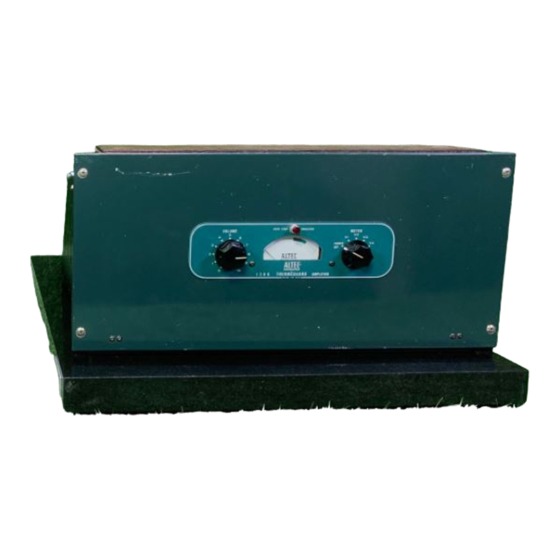
DESCRIPTION
The 128B Altec Power Amplifier is a rack-mounted AC-operated power
amplifier designed for professional recording, sound reinforcing, and
all public address applications that require low distortion over a
wide frequency range. The 128B is the deluxe counterpart of the
popular 1568A and utilizes tube metering circuits, transformer thermal
protection ("Thermeguard"), and low residual distortion over a wide
frequency range. In addition to thermal protection, the power trans-
former is fitted with a heavy copper flux shield which reduces the
AC field, allowing operation in closer proximity to low-level equip-
ment without inducing hum that would otherwise be possible. Meter
illumination, over-temperature warning indicator, switch selected
power line setting, switch controlled high pass filter, plug-in line
transformer, and speaker impedance load taps as well as the 70
volt line connection are features of the 128B design.
METERING CIRCUITS
Each of the four amplifier tubes in the 128B can be checked for space
current by means of the front panel meter (Figure 1). The right-hand
selector switch on the front panel connects the meter to the appropri-
ate meter shunt in turn as indicated by the panel marking. Meter
indication within the green area is considered satisfactory. Output
tubes, V3 and V4, conduct more current when the amplifier is driven
to full output than they do in the idle condition. The meter shunts
for these stages have been selected so that the meter normally rests
at the 100% point in the absence of signal. Although normal pro-
gram material raises the average current flow only a small amount,
it would be possible with high-level sustained tones such as from
organ reproduction to cause the meter to be pegged if the switch is
left in the V3-V4 position. It is therefore recommended that the
normal rest position be at V1
or V2.
Figure 1
Controls:
Front Panel — Volume Control,
Continuously variable composition,
Power and Meter Selection Switch
Chassis — Line Voltage Selection Switch
and High Pass Filter Switch, both
with locking plates
Power Supply:
105/125 volts, 50/60 cps, 125 watts
Tubes:
2 — 6CG7, 2 — 6CA7/EL34, 1 — 5AR4
3
Dimensions:
8
/
" High, 19" Wide, 7" Deep
4
Color:
Dark Green
Weight:
27 lbs.
Special Features:
High Pass Filter for protection of
horn-loaded drivers
Power Transformer thermally protected
("Thermeguard") against overload or
high ambient temperatures.
PROTECTIVE FEATURES
The power transformer of the 128B Amplifier is equipped with an
automatic re-setting thermal-type circuit breaker. This device is
located within the windings of the power transformer. It will sense
excessive rise of temperature due to tube malfunction, component
failure, excessively high ambient temperature due to inadequate
ventilation or the presence of other heat-producing apparatus. Should
the thermostat operate, the illuminated meter will darken and the
red over-temperature indicator directly above the meter will illumin-
ate (Figure 1). The amplifier will then automatically recycle into
operation as soon as safe temperatures have been re-established.
HIGH PASS FILTER
Horn-loaded driver loudspeakers are used in paging or voice rein-
forcing systems where excellent intelligibility is required in the
presence of high noise levels, the effects of wind and other disturb-
ances. This type of loudspeaker is limited in power handling capa-
bility below the cut-off frequency of the horn and must be protected
against excitation in this frequency range. The 128B Amplifier is
equipped with a two-section high-pass filter of the resistance capaci-
tance type. The "High Pass Filter" provides attenuation of approxi-
mately 8 db at 250 cps. The filter is inserted in the circuit by placing
the switch labeled "High Pass Filter" to the "In" position. The switch
is located on the chassis surface adjacent to vacuum tube V1 (Figure
2). To change the switch setting, remove the screw holding the lock-
ing plate so that the switch may be operated. The locking plate
should be re-assembled on the switch to prevent unauthorized or
inadvertent changing of the switch position. The locking plate is
used to hold the switch in either position by inverting the part as
required. The characteristic of the high-pass filter is shown on the
accompanying frequency response chart (Figure 4).
Advertisement
Table of Contents

Related Manuals for Altec Lansing 128B


Summary of Contents for Altec Lansing 128B
- Page 1 This type of loudspeaker is limited in power handling capa- bility below the cut-off frequency of the horn and must be protected Each of the four amplifier tubes in the 128B can be checked for space against excitation in this frequency range. The 128B Amplifier is current by means of the front panel meter (Figure 1).
- Page 2 The total of the power settings for all speakers should be equal to, or less than, the amplifier power rating. The The cabinet or other enclosure in which the 128B Amplifier is mounted 128B Amplifier is equipped with outputs to drive either a 70 volt should have adequate provisions for air entry and exit.
- Page 3 128B PARTS LIST .005 mfd ±20% Disc Erie Type 801 47,000 ohms ±10% 1.0 watt .001 mfd ±10% Disc Erie Type 831 18,000 ohms ±10% 1.0 watt .0022 mfd ±10% Disc Erie Type 801 82,000 ohms ±1% 1/2 watt Deposited Carbon .5 mfd 400 v.
Need help?
Do you have a question about the 128B and is the answer not in the manual?
Questions and answers