
Subscribe to Our Youtube Channel
Related Manuals for IDTECH SmartPIN L100

Summary of Contents for IDTECH SmartPIN L100
- Page 1 80141505-001 User Manual SmartPIN L100 Rev. H 25 March 2021 ID TECH 10721 Walker Street, Cypress, CA 90630 Voice: (714) 761-6368 Fax: (714) 761-8880...
- Page 2 ID TECH 10721 Walker Street Cypress, CA 90630 Voice: (714) 761-6368 Fax: (714) 761-8880 Copyright © 2021 by ID Technologies, Inc. All rights reserved. The information contained herein is provided to the user as a convenience. While every effort has been made to ensure accuracy, ID TECH is not responsible for damages that might occur because of errors or omissions, including any loss of profit or other commercial damage, nor for any infringements or patents or other rights of third parties that may result from this information’s use.
-
Page 3: Table Of Contents
Table of Contents 1 INTRODUCTION ............................... 6 2 FEATURES ............................... 7 3 APPLICABLE DOCUMENTS ..........................7 4 ABBREVIATIONS .............................. 8 5 SPECIFICATIONS .............................. 9 5.1 Components ..............................9 5.1.1 Faceplate Color: Silver gray Finish: Brushed finish .................. 9 5.1.2 LCD ................................9 5.1.3 LED ................................ - Page 4 8.6 Bootloader Detailed Process .......................... 30 8.6.1 Detailed Description ..........................30 8.6.1 Enter into Bootloader ..........................30 8.7 PIN Pad and MSR Pairing Solution ........................30 8.8 General Group (Task) ............................31 8.8.1 Get Firmware Release Version ......................31 8.8.2 Get Internal Firmware Version ......................32 8.8.3 Enter into Bootloader ..........................
- Page 5 10 LCD FOREIGN LANGUAGE MAPPING TABLE ....................58 11 APPENDIX A: SPECTRUM PRO RELATED COMMANDS ..................60 11.1 CR gets PINPAD UID ............................60 11.2 Get Nonce ..............................61 11.3 Get DUKPT KSN ............................. 61 11.4 Activate and Deactivate Removal Sensor ..................... 62 11.5 Handicap Assistant Signal ..........................
-
Page 6: Introduction
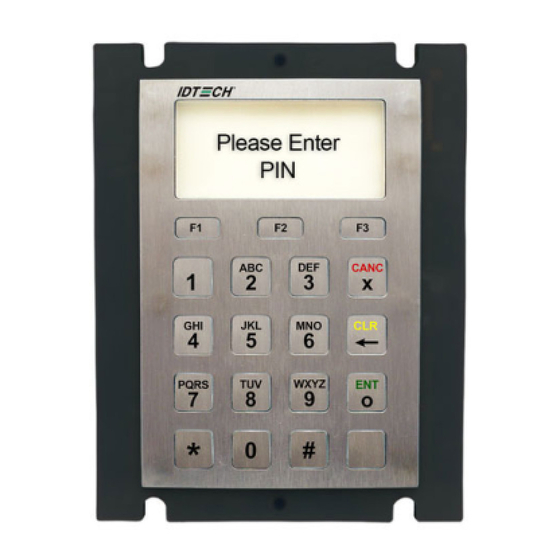
1 Introduction ID TECH’s SmartPIN L100 provides a compact, rugged, secure keypad interface for POS systems requiring PIN and/or manual-entry capability. The device’s 16-key layout and built-in LCD make it ideal for kiosks and other unattended applications. When paired with ID TECH’s Spectrum Pro insert reader, the SmartPIN L100 provides a complete, EMV-ready chip-and-PIN, chip-and-signature, debit/PIN, and MSR solution that meets ADA, ANSI, and ISO standards for PIN Entry Devices. -
Page 7: Features
2 Features PCI 4 certified • x 4 key layout (0-9, *, #, Cancel, Clear, Enter, Blank), plus 64x128-pixel liquid crystal display • function keys adjacent to the LCD • One tri-color LED on the back of the L100 to display unit status •... -
Page 8: Abbreviations
4 Abbreviations ANSI American National Standard Institute APACS Association for Payment Clearing Service API Application Programming Interface CPU Central Processing Unit DC Direct Current DES Data Encryption Standard DUKPT Derived Unique Key Per Transaction, Key management EMI Electromagnetic Interference EMV Europay, MasterCard, Visa ESD Electrostatic Discharge GND Signal Ground Host A PC or like device with local Application Software for controlling connected SmartPAY... -
Page 9: Specifications
5 Specifications 5.1 Components Faceplate 5.1.1 Color: Silver gray Finish: Brushed finish ID TECH logo LCD window 19 holes for keys 5.1.2 LCD The L100 has a liquid crystal display with four lines of 20 characters each. With 128 dots to a character, this means there are 4*20*128 (or 10,240) dots in the LCD. -
Page 10: Keys
5.1.4 Keys Color: Silver gray Finish: Brushed finish Layout: Alphabetical characters printed on the keys Operation keys have engraved, colored bar and symbols: Cancel (red), Clear (yellow), Enter (green). 3 Function Keys are etched or engraved with “F1” “F2” and “F3” respectively Tactile identifier on the numeral key 5. -
Page 11: L100 Dimensions
5.3.1 L100 Dimensions Page | 11... -
Page 12: Tamper Detection
5.4 Tamper Detection Use screw with shaft diam. 'd' such that 6 mm >= d >= 5 mm and head diam. 'D' such that 13 mm >= D >= 11 mm Tamper detect Page | 12... -
Page 13: Engaging The Removal Detection Switch For Testing
5.1 Engaging the Removal Detection Switch for Testing The front panel of the SmartPIN L100 incorporates a removal-detection switch behind the bezel's rubber gasket, on the unit's right-edge flange (when viewed head-on, as in the illustration below). Engaging the removal-detection feature is only necessary when attempting to pair an L100 with a compatible ID TECH reader, such as the VP5300. -
Page 14: Ik Test
5.5 IK Test The front face is impact resistant to meet IK9 rating (10 joules of impact energy, equivalent to dropping a 5kg object from 20 cm height). 5.6 Key Life The L100 is designed for a minimum of 2,000,000 keystroke operations per key. Page | 14... -
Page 15: Electronic Design
6 Electronic Design 6.1 Power Supply The SmartPIN L100 supports three different modes: RS232 – Requires power supplied by an external A/C power adapter (5VDC). • • UART - RJ45 cable connects directly to the Spectrum Pro insert reader; also requires an external A/C power adapter (5VDC). -
Page 16: Base Functionality
7 Base Functionality 7.1 PIN Pad function • PIN MK/SK, DUKPT Key Management • TDES Encryption (keystrokes are not sent in the clear) • 4 x 4 key layout with 0-9 numerical keys, *, #, Cancel, Clear, Enter, Blank, and 3 additional Function keys adjacent to the bottom of the LCD screen: F1, F2, F3 (function defined by application) •... -
Page 17: Nga Commands & Responses Format
8 NGA Commands & Responses format The L100 uses NGA protocol commands and responses in general communication. The format is: <STX> <Len_Low><Len_High> <Command Body / Response Body / Notification Body> <CheckLRC> <CheckSUM> <ETX> Where: • <STX> is 0x02 and <ETX> is 0x03 •... -
Page 18: Lcd & Beeper State From Deactivation State To Activation State
8.1.1 LCD & Beeper State from Deactivation State to Activation State • PK – Public Key (Manufacture Key) • FK – Firmware Key • NK – Numeric Key CV – Check Value • DTV – Date & Timer Value Device State Definition LCD Display Message Beeper State... -
Page 19: Other Lcd State For Pin Function
Device State Definition LCD Display Message Beeper State LED auxiliary indicator Activation2 Activation Ready Not beeping If not set user PK, FK, SCV, passwords: Blink NK, and DTV loaded Yellow If set user successfully passwords: At least DUKPT Key or If legally Removal MKSK is loaded State: Steady Yellow If... -
Page 20: Beeper Tone
8.2 Tamper and Failed Self-Check Indicators The SmartPIN L100 displays the following indicators when it has been tampered or has any of the other following internal issues, such as an expired certificate, missing key, or similar fault discovered during a self-check. -
Page 21: Device Operation Process
The first step is to set the device's user passwords. Part 1: Setting User Activation/Deactivation Password The SmartPIN L100 comes with two default Removal Detection passwords that need to be reset with user-generated passwords before activating the Removal Detection feature. If two user activation passwords have already been set for the L100, it beeps once and enters the “Want Fix / Removal... - Page 22 (12345678) and the device will beep to indicate complete. 2. When the LCD screen displays “Please input new password”, enter new password 1. Note that new passwords cannot be the same as the default loading key passwords. The L100 will beep short tone twice.
- Page 23 If the user enters an incorrect User Activation Password, the device will beep short tone twice – pause- short tone once and then user need to re-enter password. If the user enters an incorrect User Activation Password three times, the device will beep its Invalid Tone and suspend for three minutes.
-
Page 24: Testing With The L100
Part 4: Deactivate Removal Detection Power-on the L100 and after the device beeps once and the LCD screen displays its version message, press Cancel, Clear, Enter, Blank, Cancel, and Blank (the interval between keys cannot exceed 5 seconds). Then: 1. Enter password 1. If password 1 is entered successfully, the L100 beeps twice. 2. - Page 25 3. Click Reload APP File Path to change the directory from with the ID TECH Reader Bootload Software app loads firmware files. 4. Navigate to the directory where you downloaded the L100 firmware and click OK. Note: If you need to change the directory path for the firmware file, click the Reload APP File Path button and select a new directory to update the file list.
- Page 26 5. Select the firmware to load onto the L100. 6. Click the Update button. The ID TECH Reader Bootload Software app will update the L100 with the selected firmware. Page | 26...
- Page 27 7. Click Continue to verify the desired firmware to update. 8. The ID TECH Reader Bootload Software app displays a status bar for update progress. 9. When the update completes, the L100 will reboot and the ID TECH Reader Bootload Software app displays a Completed status and Application Update Succeeded.
-
Page 28: Updating L100 Firmware Via Serial-To-Usb Cable
8.5.2 Updating L100 Firmware via Serial-to-USB cable The steps below describe the process for updating L100 firmware via the Universal SDK Demo. Note: Before you begin, contact your ID TECH representative to receive the most recent L100 firmware. Download the ZIP file and extract it to your computer. 1. - Page 29 4. Under Device, select Update Device Firmware, then click Execute Command. 5. Navigate to and select the L100 firmware you downloaded earlier and click Open. 6. The L100 will reboot and enter the bootloader, at which point the SDK demo begins updating the device.
-
Page 30: Bootloader Detailed Process
8.6 Bootloader Detailed Process 8.6.1 Detailed Description When the L100 enters the Bootloader, the device is in the “Waiting State” with “Bootloader…” in Line 0 of the LCD display. In this state, the device can only receive the Get Version command. The expected response is the Bootloader version. -
Page 31: General Group (Task)
Response Example Response Body High 06 + [80 bytes TR-31 Block Version B Encrypted PAN Encryption Key], or 15 + failure information (see below) Response Body: 06 + [80 bytes TR-31 Block Version B Encrypted PAN Encryption Key] or 15 07 00 – No BDK of Pairing MSR Key, 15 07 03 –... -
Page 32: Get Internal Firmware Version
Response Body High 06 <Firmware Version String> Return Hex String: 022500064944205445434820536d61727450494e204c313030204669726d776172652056312 e30303a7403 <STX> <length byte low><length byte high> <ACK>ID TECH SmartPIN L100 Firmware V1.00 <LRC><SUM> <ETX> 8.8.2 Get Internal Firmware Version Command Body: 78 31 Response Example Response Body High 06 <Firmware Version Number>... - Page 33 Response Body High 06 <10-digit serial number> Response Hex String: 020b000636313654353638393432673903 <STX><len low><len high><ACK><10-byte serial number><LRC><SUM><STX> The LRC and SUM will obviously depend on the model number. Page | 33...
-
Page 34: Get Model Status
8.8.5 Get Model Status Command Body: 78 46 20 Command Example Command Body High 78 46 20 Output Hex String: 0203007846201ede03 Response Body: 06 + Model Status 8.8.6 Response Example Response Body High 06 <model status> Response Hex String: 020d0006494450422d3630323430304d79cb03 <STX><len low><len high><ACK><model number><LRC><SUM><STX>... -
Page 35: Get Key Status
Response Body: 06 <2-byte Block Length> <KeyStatusBlock1> <[KeyStatusBlock2]> … <[KeyStatusBlockN]>, Or 15 <Error Code> Response Example Response Body High 06 <Block Length Low><Block Length High> <KeyStatusBlock1> <[KeyStatusBlock2]> … <[KeyStatusBlockN]> Response Hex String Example: 0263000618000000000001000000030000000400000006000000070000000800000008000100 080002000800030008000400080005000800060008000700080008000800090008000a000800 0b000a0000000a03e8000c0000000d0000001400000128000000ce2a03 Where: <Block Length> - 2 bytes (LenL, LenH) KeyStatusBlock format is <Key Index and Key Name>... -
Page 36: Set Remote Key Injection Timeout
Response Body: 06 + PIN DUKPT Status + PIN Master Key Status + PIN Session Key Status + Account DUKPT Key Status + AccountDUKPT Key Status + RKI-KEK (Admin DUKPT Key) Where: Status Note 0: None. 1: Exist 0xFF: STOP PIN Encryption Key PIN Master Key 0: None... -
Page 37: Get Remote Key Injection Timeout
8.8.11 Get Remote Key Injection Timeout Command Body: 78 52 01 01 Command Example Command Body High 78 52 01 01 Output Hex String: 020400785201012acc03 Response Body: 06 78 01 01 02 <Timeout_H> <Timeout_L> Response Example STX Len Response Body High 78 52 01 01 02 00 C0 Output Hex String: 020700067801010200c0bc4203... -
Page 38: Get Date & Time
8.8.13 Get Date & Time Command Body: 78 52 01 50 16 05 20 10 26 01 Command Example Command Body High 78 52 01 50 Output Hex String: 020400785201507b1b03 Response Example Response Body High 06 78 01 50 06 16 05 10 13 16 19 Output Hex String: 020b000678015006160510131619364203 Which is STX, 2 length bytes, ACK + 78 01 50 06 + <Data Time>... -
Page 39: Enter Stop Mode
o <State> is 0x30 (Fix) or 0x31 (Removal) or 0x32 (Illegal Removal) Year, Month, Date, Hour, and Minute need be ASCII code. Note: The Max Records is 40. After response this command, all Records are deleted. 8.8.15 Enter Stop Mode Command Body: 78 46 72 01 Command Example Command Body... -
Page 40: Other Pin Pad Group (Task)
3. Bootloader mode, Diagnosis mode, Get PIN, Get Numeric, Get Function Key, Get PIN for Pro, Display and Get Key for Pro and Active PINpad, Activate/Deactivate Passwords, load cert, load key and load important data for PINpad cannot enter sleep mode. 8.9 Other PIN Pad Group (Task) 8.9.1 Get Encrypted PIN Command Body: 75 46 07 <KeyType><PAN (Account#)><LCD len><LCD Command format>... -
Page 41: Get Numeric With Display Message
Per 10 Seconds, if the PIN length was not zero, the PIN would be clear. While you press numeric key, Device will increase display "*" on LCD if Total PIN length is smaller than 12. Line 1 display: If Enter 2 numeric: ** •... -
Page 42: Displaymessage And Get Numeric Key
smaller than MaxLen. . Line 1 display: o If Enter 2 numeric (12): 12 or ** o If Enter 16 numeric (1234567890123456): 1234567890123456 or **************** While you press Backspace key, Device will decrease display numeric on LCD if Total numeric •... -
Page 43: Get Function Key
< min_len>- the max length for numeric. Max length cannot be less than 1 • <256 bytes Encrypted Display Message> is encrypted Plain text data by numeric key using RSA- • 2048 algorithm. The plain text of <256 bytes Encrypted Display Message> format is: <LCD Message len><LCD Message Data>... -
Page 44: Beeper Control
Command Example Command Body High 75 46 09 Output Hex String: 0203007546093AC403 Note: Use this command to Cancel “Get Func Key” & “Get Encrypted PIN” & “Get Numeric” & “Get Amount” Response Body: always 15 18 00 8.9.7 Beeper Control Open / Close Beeper: Command Body: 75 46 01 01 <On/Off>... -
Page 45: Set Pin Len
8.9.8 Set PIN Len Command Body: 75 53 01 01 02 MinLen MaxLen Command Example Command Body High 75 53 01 01 02 MinLen MaxLen Output Hex String: 0207007553010102040A2ADA03 MinLen need be 4~12 MaxLen need be 4~12 MinLen need be same or less than MaxLen Response Body: 06 8.9.9 Get PIN Len Command Body: 75 52 01 01... -
Page 46: Get Numeric Len
8.9.11 Get Numeric Len Command Body: 75 52 01 02 Command Example Command Body High 75 53 00 Output Hex String: 0204007552010224CA03 Response Body: 06 75 01 02 02 MinLen MaxLen 8.9.12 Default PINpad Group All Setting Command Body: 75 53 00 Command Example Command Body High... -
Page 47: Manual Pan Entry Support
8.9.14 Manual PAN Entry Support Command Body: 75 46 06 <Para> Where: Para is 1 byte. Bit0 User does not input CVV data. User inputs CVV data. Bit1 User does not input ADR data. User inputs ADR data. Bit2 User does not input ZIP data. User inputs ZIP data. -
Page 48: Real Time Key Press Support
8.9.15 Real Time Key Press Support This command sets output data content for the Get PIN, Get Numeric Key, and Get Amount commands. Command Body: 75 46 25 & <1-byte parameter> Where: • Parameter = 0: when a Get PIN, Get Numeric Key, or Get Amount command is executed, the device outputs “06 57 46 50 47”... - Page 49 key using RSA-2048 algorithm. Plaintext display message format is: <Len> <Flag> <Display Message String> • o <Len>: 1 byte, the length of Display Message String o <Flag>: 1 byte, the Display Option of Line2 o Bit0 = 0: When the user presses a numeric key, the L100 increments the numbers on the ...
-
Page 50: Lcd Group (Task)
When a Cancel command is sent, the L100 quits the work state. • The response body depends on the command (75 46 25). If the related parameter is not 0, the • response data is only the ASCII code for the pressed keys. 8.1 LCD Group (Task) 8.1.1 Clear Display Command Body: 8A 46 01 <Control>... -
Page 51: Save Prompt Display
8.1.2 Save Prompt Display Command Body: 8A 46 24 <Prompt> <Message> Where: • <Prompt> - Prompt number 0 – 9 • <Message> - display message 20 char MAX ((ASCII Code – 0x20~0x7F)) Command Example Command Body High 8A 46 24 <Prompt> <Message> Output Hex String: 020c008a4624022a2a2a2a2a2a2a2aea4603 Example shows Prompt 2, Message "********"... -
Page 52: Default Lcd Group All Setting
<Line> - Display line number 0 Or 1 or 2 or 3 • <1~20 Message > - Message (ASCII Code – 0x20~0x7F) The example above sets the message "SmartPIN L100 Ready" Response Body: 06 8.1.5 Default LCD Group All Setting... -
Page 53: Set Back Light Of Lcd On/Off
Response Example Response Body High 06 8A 04 01 <Back Light Control>05 01 <TimerValue> Output Hex String: 020500068a040101889603 8.1.7 Set Back light of LCD On/Off Command Body: 8A 53 01 04 01 <Control> Where: <Control>: • 0: OFF • 1: ON Response Body: 06 8.1.8 Get Back light of LCD On/Off Command Body: 8A 52 01 04... -
Page 54: Get Baudrate
8.2.2 Get BaudRate Command Body: 70 52 01 41 Command Example Command Body High 70 52 01 41 Output Hex String: 02040070520141620403 Response Body: 06 70 41 01 <ASCIIChar> Command Example Command Body High 06 70 41 01 <Speed> Output Hex String: 020500067041013701ef03 BaudRate ASCIIChar 2400... -
Page 55: Get Stopbits
8.2.4 Get StopBits Command Body: 70 52 01 45 Command Example Command Body High 70 52 01 45 Output Hex String: 02040070520145660803 Response Body: 06 70 45 01 + <ASCIIChar> Page | 55... -
Page 56: Error Codes
9 Error Codes Error Code Definition 0x0100 Log is full 0x0400 Related Key was not loaded 0x0500 Key Same 0x0501 Key is all zero 0x0502 TR-31 format error 0x0700 No BDK of Pairing MSR Key 0x0701 Have BDK of Pairing MSR Key, Not Pairing with MSR (No PAN Encryption Key) 0x0702 PAN is Error 0x0703... - Page 57 0x7600 Device is in Transparent Transmission mode 0x8100 Timeout 0x8200 Wrong operate step Page | 57...
-
Page 58: Lcd Foreign Language Mapping Table
10 LCD Foreign Language Mapping Table ID Message ID English French Spanish Chinese MSG_NULL MSG_AMOUNT AMOUNT MONTANT CANTIDAD 金额 MSG_AMOUNT_OK AMOUNT MONTANT OK MONTO 确定金额 CORRECTO? MSG_APPROVED APPROVED APPROUVE APROVADO 通过 MSG_CALL_YOUR_BANK CALL YOUR BANK APPE VOTRE LLAME A SU 请联系您的... - Page 59 22 MSG_TRANSACTION_ERR TRANSACTI ERREUR DE ERROR DE 交易错误 ON ERR TRANS TRANSAC 23 MSG_TERMINATE TERMINATE RESILIER TERMINAR 终止 24 MSG_ADVICE ADVICE CONSEILS CONSEJOS 建议 25 MSG_TIMEOUT TIME OUT TIMEOUT TIEMPO DE 超时 ESPERA 26 MSG_PROCESSING PROCESSING PROCESSUS... PROCESAND O... 处理 中。。。...
-
Page 60: Appendix A: Spectrum Pro Related Commands
11 Appendix A: Spectrum Pro Related Commands Note: The Length in the message blocks of following commands and responses all has the formatted as 2-byte, little-endian. Card Reader is abbreviated CR. 11.1 CR gets PINPAD UID Command: Task ID '65' or ‘56’ ‘46’... -
Page 61: Get Nonce
11.2 Get Nonce Command: Task ID '65' or ‘56’ ‘46’ Function ID '27' Length Length of data Data • Length of NONCE • CR NONCE, 16 bytes Response: Result byte If success, return ACK. If failed, return NAK <Error Code> Task ID '56' or ‘65’... -
Page 62: Activate And Deactivate Removal Sensor
Data • Key Index, 1 byte: 0x0 –Host-PINPAD Master DUKPT Key 0x1 –PIN DUKPT Key 0x3 –PIN Pairing DUKPT Key 0x4 –Data Pairing DUKPT Key 0x6– CR-PINPAD Master DUKPT Key 0x7–CR-PINPAD MAC DUKPT Key 0xA– RKL DUKPT Key 0xC–RKI-KEK (Admin DUKPT Key) 0x14 –... - Page 63 Response: Result byte If success, return ACK. If failed, return NAK <Error Code> Task ID '67' or '65' Function ID ‘45’ Length Length of data Data If Card Reader command checks pass, else data not present. • Length of MAC -CR •...
-
Page 64: Handicap Assistant Signal
11.5 Handicap Assistant Signal Output: Result byte Task ID '57' ‘46’ Function ID ‘50’ Length Data None Note: This command is used to respond with buzzer beeps for a key pressed, and it just responds when connected with host. This command applies to following commands: Get Encrypted PIN •... - Page 65 • Length Display Message Language • Display Message Language, 2 bytes: EN - English (default) ES – Spanish ZH – Chinese FR - French • Length Display Message Control (0-No Message display) • Display Message Control: repeatable combination of <Line><Message><0x1C> •...
-
Page 66: Get Pin (Command Only Between Cr-Pinpad)
Response: Result byte If success, return ACK. If failed, return NAK <Error Code> Task ID '52’ ‘46’ Function ID ‘B0’ Length Length of data Data • Display mode 0: Cancel (user presses cancel key on the keypad for mode 1, 4 and 5) 1: Menu Display 2: Normal Display get function key 3: Display without key input... - Page 67 Length Length of data Data • Mode byte: 0x00 – Cancel (cancel through command) 0x01 - Online PIN DUKPT (0x81 for NON-PINBYPASS) 0x02 - Online PIN MKSK (0x82 for NON-PINBYPASS) 0x03 - Offline PIN (0x83 for NON-PINBYPASS) • If Mode byte is “Cancel”, the field below is unnecessary. •...
-
Page 68: Plain Text Of Truncated Primary Account Number (Pan) Pack
• Length Enciphered PIN • Enciphered PIN • Length KeyID (If Desjardins Session is loaded) • KeyID (If Desjardins Session is loaded) • Length MAC-PINPAD • MAC- PINPAD 180 seconds is the suggested timeout for starting PIN input. After PIN input starts, 20 seconds the suggested timeout for finishing PIN input. - Page 69 Note: Yellow: Optional block-KeyIndex Green: Optional block-KeySlot Red: Optional block-KSN/KeyID KBH for Master DUKPT Key: B0136B1TX00E03000108000002080000KS18FFFF9876543210E00000 KBH for PIN DUKPT Key: B0136B1TX00E03000108000102080000KS18FFFF0000000000000000 MK/SK PIN Master Key: B0112K0TB00E02000108000802080000 DATA Pairing DUKPT Key: B0136B1TX00E03000108000402080000KS18FFFF0000000000000000 PIN Pairing DUKPT Key: B0136B1TX00E03000108000302080000KS18FFFF0000000000000000 Command: Task ID '65’...
-
Page 70: Set Working Key
errorMessage = (PRINTABLESTRING) KCV = (OCTET STRING) -- 3 bytes, algorithm refer to x9.24 11.8.2 3C – Set Working Key Working key includes PIN/PIN Master /PIN Pairing/ Data Pairing/ MAC Key. This command should be issued after the Card Reader and PINPAD have established the CR_PINPAD_MASTER_DUKPT_KEY. - Page 71 Response 1: Result byte If success, return ACK. If failed, return NAK <Error Code> Task ID '67' or '56' or '57' ‘46’ Function ID ‘3C’ Length Length of data Data KCV ASN.1 structure KCV ASN.1 structure::= Sequence { KCV ASN.1 structure version = 1 (INTEGER) Keys ::= Set { keyinfo ::= Sequence { keyName = (PRINTABLESTRING) errorCode = (INTEGER) --‘0’...
-
Page 72: Appendix B: Opos/Jpos
12 Appendix B: OPOS/JPOS OS: Windows 7 or later, 32 bit and 64 bit UPOS version: 1.14 JRE : Java 8 or later Both OPOS and JPOS are supported. 12.1.1 Methods, Properties and Events AutoDisable Unsupported CapCompareFirmwareVersion Unsupported CapPowerReporting Unsupported CapStatisticsReporting Unsupported CapUpdateFirmware... - Page 73 DeviceServiceDescription Full DeviceServiceVersion Full PhysicalDeviceDescription Full PhysicalDeviceName Full CapDisplay Full CapKeyboard Unsupported CapLanguage Full CapMACCalculation Unsupported CapTone* Unsupported AccountNumber Full AdditionalSecurityInformation Full Amount Full Currency Full AvailableLanguagesList Full AvailablePromptsList Full EncryptedPIN Full MaximumPINLength Full MerchantID Full MinimumPINLength Full PINEntryEnabled Full Prompt Full PromptLanguage...
- Page 74 enablePINEntry( ) Full endEFTTransaction ( Full completionCode ) updateKey ( keyNum, key ) Unsupported verifyMAC ( message ) Unsupported Events (UML interfaces) uposeventsDataEvent Full uposeventsDirectIOEvent Unsupported uposeventsErrorEvent Full uposeventsStatusUpdateEvent Unsupported *Full: this item is fully supported and functional. *Unsupported: this item is either not supported or disabled. Page | 74...
-
Page 75: Appendix C: Clearing The Log
13 Appendix C: Clearing the Log The SmartPIN L100 maintains a log file of administrative events. When this log file becomes full (after approximately 45 logged events), the L100 may fail to enter the Removal Detection mode or may beep twice, then pause, then beep once, when the user attempts to enter a password (indicating that the Log is full). - Page 76 6. Verify that the command was sent (item 4), and that the response includes ACK (06). If you receive a "Send Command Fail Error Code: 0x3: time out for task or CMD" response, make sure your L100 is powered and awake. Repeat the command if necessary. 7.
Need help?
Do you have a question about the SmartPIN L100 and is the answer not in the manual?
Questions and answers