Advertisement
Quick Links
Advertisement

Related Manuals for Adesys SVA

Summary of Contents for Adesys SVA
- Page 1 Manual SVA Version 02-2021 MEASURING - ALERTING - CONNECTING...
- Page 2 Adesys B.V. | Wateringen Index Introduction 1.1. Variants 1.2. Features of the SVA-series 1.3. Safety criteria 1.4. Checking the delivery 1.5. Environment 1.6. Warranty and repair 1.7. Liability 1.8. Identification Connection 2.1. Positioning 2.2. Affixing and removal: DIN rail 2.3. SIM card 2.4. Antenna 2.5.
- Page 3 • To reduce the probability of damage to the equipment, the SVA should be placed in an environment protected against electrostatic discharge (ESD). • The SVA is intended for use as a modem or alarm dialler. The SVA is not intended for use as part of a critical safety system in a critical process.
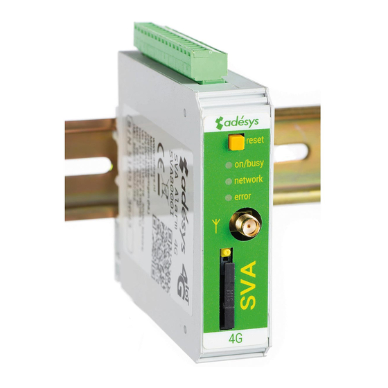
- Page 4 Identification Figure 1 Identification SVA Reset button LED status indicator: general status (on/busy), antenna level (network), error messages (error) Antenna connection type SMA female SIM card holder Ethernet connection Information sticker Input/output connection terminals Supply voltage connection terminals Connection sticker DIN rail mounting clamp Manual SVA alarm dialler | Back to Index Page 4...
- Page 5 Positioning Position the SVA where it is not affected by direct sunlight or other heat sources. Choose the place of installation such that moisture cannot penetrate the device. The SVA can be mounted onto the TS35 rail without screws. The permitted ambient temperature range for the electronics is -20°C to +50°C. The transmission power of the SVA’s internal GSM/4G module is higher than that of a standard mobile phone. Under certain conditions this may affect the functioning of surrounding electronic equipment. The...
- Page 6 If the SVA is restarted manually, this status will also be reset. When the supply voltage is restored, the SVA behaves as if it is being started up for the first time. This means that: •...
- Page 7 Connect the SVA to a power source and connect the SVA to the PC using the Ethernet cable set supplied. The SVA can be connected to the local network or directly to the PC. As soon as the SVA has been switched on, the tool will display this in the overview after a few seconds and the SVA can be configured by clicking it. When search diallers is pressed, SV-prog shows all accessible diallers.
- Page 8 POST and the settings via MQTT. For more information please contact Adésys. 3.6. System In the system section you can change the general SVA settings, enter GSM and mobile data settings or trigger a factory reset. 3.6.1. Device In this window you can change device-specific settings such as device name, alarm active text, alarm recovery text, automatic updates, periodic reset and a periodic report.
- Page 9 After receiving the alarm message, an acceptance SMS should be sent back. The content of this message does not matter as the SVA uses number recognition to accept the SMS. 4.4. Notification of mains power failure The SVA is equipped with a supercap. This gives the dialler the option of sending a few messages in the event of a power failure. The associated notification message is sent to the first number in the call list linked to the mains power failure. Any set acceptance time is ignored. This means that sufficient power is present in the powercaps to execute the reports.
- Page 10 Idle. Output switching by SMS With the SVA, the output channel can be switched by means of an SMS message. The SMS message should be structured as follows: #<Command><parameter1><parameter2># • Command = O (Output). • Parameter1 = A (Active) or I (Idle) or P (switch Pulse, default: 2 seconds active). • Parameter2 = I/O number.
- Page 11 Type of detector: alarm dialler | (Weblogger|modem) Number of digital inputs Number of GPIO inputs Number of PT100 inputs Number of relay outputs I=4G variant Input/output options (differs for each SVA model) Digital contact input (NO/NC) 4 - 8 Digital voltage input (5 - 24VDC ) 4 - 8 Relay outputs 0 - 2...
- Page 12 EN 60950-1 (2006) + A11 (2009) + A1 (2010) + A12 (2011) + AC(2011) + A2 (2013) Alert functions Number of dialing 3 call lists, each containing 8 dialing numbers per call list, maximum of 20 numbers digits per dialing number Notifications SMS message or text message over IP IP network Manual SVA alarm dialler | Back to Index Page 12...
- Page 13 Checkmyprocess.com Industrial 4G Weblogger for Industrial 4G modem/sms Convenient display of current sending alerts in relation to limit alarm dialler for connection to measured values from values being exceeded. applications in the field. your process. Visit the SVA product page on the website Version 02-2021...
Need help?
Do you have a question about the SVA and is the answer not in the manual?
Questions and answers