Table of Contents
Advertisement
Advertisement
Table of Contents

Related Manuals for LEM SATURN GEO X


Summary of Contents for LEM SATURN GEO X
- Page 1 Operating Instructions EARTH GROUND TESTER SATURN GEO X...
- Page 2 SATURN GEO X BASIC SET A188506510 Incl.2 safety measuring leads with test tips and crocodile clips, 6 batteries, carrying strap, manual. SATURN GEO X with INTERFACE and A188506512 GEO-MEASURING-SET 4pole Incl.2 safety measuring leads with test tips and crocodile clips, 4 earth stakes,3 reels with 2x25m and 1x50 m wire, Interface, Set-up Software, RS232 cable &...
-
Page 3: Table Of Contents
Contents SAFETY INSTRUCTIONS ................2 FIRST SETUP ....................3 GENERAL ....................4 ASSEMBLY ....................6 DESCRIPTION OF FUNCTIONS..............7 TECHNICAL DATA ..................9 DESCRIPTION OF THE OPERATING ELEMENTS........19 PROCEDURE OF MEASUREMENTS............22 General ....................... 22 Measurement of interference- voltages and frequencies ......28 Measurement of earthing resistances ............ -
Page 4: Safety Instructions
1 SAFETY INSTRUCTIONS This measuring equipment is only to be operated by qualified staff and in accord with its technical data in compliance with the safety precautions and instructions set forth below. In addition, use of this equipment requires compliance with the legal and safety instructions pertaining to the specific application in question. -
Page 5: First Setup
2 FIRST SETUP Unpacking When unpacking the instrument watch out for possible damages that may have occurred during transport. In the case of defects the packing material must be kept until the complaint is adjusted. Keep the packing material also in case you need it to transport the instrument at a later date. -
Page 6: General
3 GENERAL Microprocessor controlled universal earth resistance meter with fully automated measuring frequency selection process as well as automatic testing of probe- and auxiliary earth electrode resistances and possible interference voltages as per DIN IEC61557-5/EN61557-5. - Measurement of interference voltage (U ST ) - Measurement of interference frequency (F ST ) - Measurement of probe resistance (R S ) - Measurement of auxiliary earth electrode resistance (R H ) - Page 7 The instrument can be upgraded by using optional devices: An external current transformer with a transformation ratio between 80 and 1200:1 for the measurement of a single branch in mesh operated earthing systems is available as an option and enables the user to measure on high voltage pylons without seperating the overhead earth wires or earth strips at the bottom of the pylons and also to measure lightning protection systems without seperating the individual lightning protection wires.
-
Page 8: Assembly
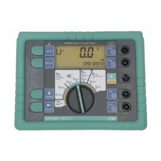
4 ASSEMBLY The instrument is made up of two parts: 1) The base part which contains the entire measuring electronics. 2) The protective housing with attachable carrying strap. The functions are selected with the central rotary switch. Four rubber buttons,which start measurements, read out supplementary measuring values and select special functions, are located on the left hand side of the front panel. -
Page 9: Description Of Functions
5 DESCRIPTION OF FUNCTIONS Measurement of interference voltage (U ST ) Fullwave rectification for DC and AC (DC without operational sign, AC signal sinus calibrated for r.m.s. values). If limit values are exceeded no measurement will be started. Measurement of interference frequency (F ST ) For interference voltage >1V its frequency is derived from the period time. - Page 10 Measurement of earthing resistance (R E ) The earthing resistance is determined by a 3- or 4-pole current and voltage measurement. The measuring voltage is a square pulse AC voltage with 48 / 20 V and a frequency of 94 ,105 , 111 or 128 Hz. The frequency can be selected manually or automatically (AFC) .
-
Page 11: Technical Data
6 TECHNICAL DATA General: Microprocessor controlled, fully automated earth measuring instrument with additional functions Measuring function: interference voltage and frequency, earthing resistance 3- and 4-pole with / without clip-on current transformer, resistance 2-pole with AC, 2- and 4-pole with DC Display: 4 digit (2999 Digit) - 7 segment liquid crystal display, digit size 18 mm with supplementary... - Page 12 − system voltages between 85 % and 110 % of the nominal voltage and between 99 % and 101 % of the nominal system frequency for measuring equipment with a mains supply and/or measuring equipment deriving its output voltage directly from the distribution system.
- Page 13 Measurement of interference voltage DC + AC (U ST ) Measuring method: fullwave rectification Measuring Display Resolution Frequency range Limits of error range range 1…50 V 0.0…50 V 0.1 V DC/AC 45…400 Hz sine ± (5% of mv +5 digit) Measuring sequence: approx.
- Page 14 Earthing resistance (R E ) Measuring method: current and voltage measurement with probe as IEC61557-5/EN61557-5 Open circuit voltage: 20 / 48 V, AC Short circuit current: 250 mA AC Measuring frequency: 94 , 105 , 111 , 128 Hz selected manually or automatic.(AFC) 55 Hz in function R* Noise rejection: 120 dB ( 16...
- Page 15 100 Ω 30.0 kΩ...299.9 kΩ Measuring time: typ. 8 sec. with a fixed frequency 30 sec. max. with AFC and complete cycle of all measuring frequencies Additional error because of probe-and auxiliary earth electrode resistance: Ω 2000 − × × 125 10 digits Measuring error of R H and R S :...
- Page 16 Automatic switchover of measuring resolution in dependence to auxiliary earth electrode resistance R H : R H with Umeas = 48 V R H with Umeas = 20 V Resolution < 300 Ω < 250 Ω 1 m Ω 10 m Ω <...
- Page 17 Minimal current in single branch 0.5 mA with transformer (1000 :1) to be measured: 0.1 mA with transformer (200 :1) Max. interference current through transformer: with a transformer (1000:1) Resistance measurement (R ˜ Measuring method: current and voltage measurement Measuring voltage: 20 V AC, square pulse Short circuit current: >...
- Page 18 300 Ω ... 2999 Ω 1 Ω...
- Page 19 Measuring sequence: approx. 2 measurements/s Measuring time: typ. 4 sec. incl. reversal of polarity (2 pole or 4 pole) ≤ 3 V AC or DC, with higher voltages measurement will Max. interference voltage: not be started Max inductivity: 2 Henry Max.
- Page 20 back / Rückseite / derrière...
-
Page 21: Description Of The Operating Elements
7 DESCRIPTION OF THE OPERATING ELEMENTS Central rotary switch to select measuring function or switch ON/OFF "START" -button to start the set measuring function. "DISPLAY" -button to call corresponding supplementary values. "CHANGE " button to change the set point entry values "SELECT "... - Page 22 Description of display elements The display is divided into four display elements: 1. Digital display of measured value 2. Measuring function field to display measuring function 3. Unit field: V, Ω, kΩ, Hz 4. Special characters for operator guidance Description of display symbols Interference voltage (AC + DC) Frequency of interference voltage Frequency of measuring voltage...
- Page 23 REMOTE Interface ( optional ) active - button operation locked Measuring circuit ( E-S,E-H ) interrupted or measured value instable WARNING: Refer to operating instructions...
-
Page 24: Procedure Of Measurements
8 PROCEDURE OF MEASUREMENTS WARNING: Use the instrument on voltage free systems only Operation is easy : Set measuring function with the central rotary switch Connect instrument ! without measuring lead connected START is omitted ! Start measurement with "START" button read out measured value. - Page 25 d) Number of software version By keeping the "SELECT " button pressed during the switch on sequence, the number of the software version is indicated on the display. By pressing the "DISPLAY" button a switch over to the last calibration date is possible. This display sequence is terminated by turning the central rotary switch or pressing the "START"...
- Page 26 8.1.2 Operation The measuring functions have two initial operational modes: The Control loop and the Measuring loop Operation flow chart :...
- Page 27 Control loop: After turning the function rotary switch, the voltage display mode is reached. Pushing "DISPLAY" now calls up the control loop. According to the selected measuring function, different setting values can be displayed and changed in the control loop. The "DISPLAY"...
- Page 28 Function Parameter Setting range Remarks display only display only (AFC/94/105/111/128)Hz 0.000 Ω ... 29.99 Ω 0.000 Ω ... 999 kΩ R ~ LIMIT only if activated with CODE On / Off only if R ~ LIMIT (warning- sound) is activated with CODE display only R ...
- Page 29 8.1.3 Checking of correct measuring connection (socketallocation) The instrument implements an automatic check, corresponding to the measurement selected, to see if the correct input sockets are used. The display symbols and are assigned to the corresponding sockets. From the way the symbols are displayed, the correctness of the connected wiring can be concluded by the following features: •...
-
Page 30: Measurement Of Interference- Voltages And Frequencies
8.2 Measurement of interference- voltages and frequencies This measuring function detects possible interference voltages and their frequencies. This function is automatically active in every switch position before an earthing or resistance measurement. If the pre-set limit values are exceeded, the interference voltage is indicated as to high and a measurement automatically prevented .The frequency of an interference voltage is only measurable if the level of this intereference voltage is higher than 1 V. -
Page 31: Measurement Of Earthing Resistances
8.3 Measurement of earthing resistances This instrument is equipped with a 3 pole as well as a 4 pole resistance measurement which renders measurements of resistances of earthing systems possible, as well as measurements of the soil resistivity of geological strata. A specific description of the different applications is given further on in this manual. - Page 32 8.3.1 3-pole/4-pole measurement of earthing resistance This measuring function measures earthing and earth dissipation resistances of single earth electrodes, foundation earth electrodes and other earthing systems by using 2 earth spikes. Measuring process: Turn central rotary switch to position "R E 3pole" or "R E 4pole" The instrument is to be wired according to picture and notices given on the display.
- Page 33 An accuracy test of the results is made with another measurement following repositioning of the auxiliary earth electrode or probe. If the value stays the same, the distance is sufficient. If the measured value changes, probe or auxiliary earth electrode must be repositioned until the measured value R E stays constant. Spike wires should not run too close.
-
Page 34: Measurement Of Single Earth Electrode Resistances In Mesh Operated Earthing Systems
8.4 Measurement of single earth electrode resistances in mesh operated earthing systems This patent pending measuring method has been created to measure single earth electrodes in permanently wired or mesh operated systems (e.g. lightning protection system with several electrodes or high voltage pylons with earth cabling etc.). By measuring the actual current flow through the earth electrode, this special measuring method provides the unique possibility to measure selectively only this particular resistance by means of a clip-on transformer (accessory). - Page 35 8.4.1 3-pole/4-pole measurement of single earth electrode resistances Measuring process: Turn central rotary switch to position " RE 3pole" or " RE 4pole". The instrument is to be wired according to picture and notices given on the display. A flashing of the sockets symbols , points to an incorrect incomplete connection of the measuring lead.
- Page 36 Remarks for the setting of earth spikes: Before setting the earth spikes for probe and auxiliary earth electrode make sure that the probe is set outside the potential gradient of earth electrode and auxiliary earth electrode (see also 12.5).Such a condition is normally reached by allowing a distance of >20m between the earth electrode and the earth spikes as well as to the earth spikes to each other.
- Page 37 8.4.2 Measurements on high voltage pylons 8.4.2.1 Measuring the earthing resistance without disengaging the overhead earth wire The measurement of the earth resistance of a single high voltage pylon usually requires the overhead earth wire to be disengaged (lifted off) or the seperation of the earthing system from the pylon construction.
- Page 38 Measuring process: Turn central rotary switch to position ” R E 3pole " or ” R E 4pole " The instrument is to be wired according to picture and notices given on the display. A flashing of the sockets symbols , points to an incorrect or incomplete connection of the measuring lead.
- Page 39 Apply current transformer to next pylon stub. Repeat measuring sequence. Current feeding point of measuring current (alligator clip) and the polarity of the split core current transformer has to be left unchanged. After values of R Ei of all pylon foots are determined, the actual earth resistance R E has to be calculated : Note: If the displayed R E value is negative despite correct orientation of the current...
- Page 40 8.4.3 Correcting clip-on transformer errors If the measurement of an earthing resistance by means of a clip-on transformer results in a significantly different value as if measured without the clip-on, the deviation may be due to the tolerances of the clip-on current transformer. This error can be corrected by fine tuning the clip-on transformation ratio (basic settings 1000:1).
- Page 41 If the thus measured value R E deviates from the R E value determined without clip-on transformer by more than 5%, adjust the clip-on transformation ratio (tr) correspondingly: − R with clip on transformer × − R without clip on transformer Example: Your clip-on transformer has a transformation ratio of tr = 1000:1.
- Page 42 8.4.4 Compensation of earth electrode connecting lead If the line resistance to the earth electrode can not be ignored, a compensation of the connecting lead resistance to the earth electrode is possible. Proceed as described below: Measuring process: Turn central rotary switch to position "R E 3pole" Wire instrument according to picture Call display R K with "DISPLAY"...
-
Page 43: Measurement Of Soil Resistivity
8.5 Measurement of soil resistivity The soil resistivity is the geological and physical quantity for calculation and design of earthing systems. The measuring procedure applied below uses the method developed by Wenner (F.Wenner, A method of measuring earth resistivity; Bull. National Bureau of Standards, Bulletin 12 (4), Paper 258, S 478-496;... - Page 44 The measuring method according to Wenner determines the soil resistivity down to a depth of approx. the distance "a" between two earth spikes. By increasing "a", deeper strata can be measured and checked for homogenity. By changing "a" several times, a profile can be measured from which a suitable earth electrode can be determined.
-
Page 45: Measurement Of Resistances
8.6 Measurement of resistances 8.6.1 Resistance measurement (R~) This measuring function determines the ohmic resistance between 0.001 Ω and 300 kΩ. The measurement is done with AC voltage. For measurements of very low resistances a compensation of the connecting leads is suggested (see 8.6.3). Measuring process: Turn central rotary switch to position "R~"... - Page 46 8.6.2 Resistance measurement ( R In this measuring mode all resistances from 0.001 Ω to 3 kΩ can be measured with DC voltage and automatic polarity reversal as per VDE 0413/part 4 To achieve highest accuracy 4 pole measurements are possible. To balance the extension lead, a compensation has to be done.
- Page 47 Evaluation of measured value: Taking into account the maximum operating error, the diagrams show the maximum admissable display values to be displayed so not to exceed the required resistance. Measuring Range 29,99 ... 299,9 ... 2999 Ω 8.6.3 Compensation of measuring lead resistance Call display of R K with button "DISPLAY"...
-
Page 48: Changing Of All Data Settings With Personalized Code
8.7 Changing of all data settings with personalized CODE With this function (F M , U M -Limit, Limit, beeper, ratio, R*, F*) limit- and set values can be programmed which keeps them memorized even if the instrument is switched ON/OFF. - Page 49 TO STORE A CODE Press all 4 keys simultaneously and move central selector from OFF to the desired measuring mode. The display shows " C _ _ _ ". Now enter the CODE-number. Any three-digit number can be entered. NOTE: Once a CODE has been entered, all subsequently programmed values can only be changed after entering the CODE number.Once a "CODE"...
- Page 50 TO DELETE A CODE : Press all 4 keys simultaneously and move central selector from OFF to any measuring mode. The display shows " C _ _ _ ". Now enter the existing CODE-number. Inputing the code is done by means of the " CHANGE "...
-
Page 51: Description Of Displays
9 DESCRIPTION OF DISPLAYS Function Displays Condition Note Stand by Turn rotary Before position to switch or "START" reduce power push button. consumption All measured values remain stored No or Apart from incorrect voltage measuring measurement lead all measuring connection functions are locked! Battery... - Page 52 Function Displays Condition Note Before Rotary switch "START" Select correct intermediate position! position After "START" Probe Wait for test resistance is result! being tested Aux. current spike- Wait for test resistance is result! being tested Earth Wait for test resistance is result! being tested.
- Page 53 Function Displays Condition Note After "START" Measuring Measured range value is exceeded. higher than 300 kΩ. Display of Measured measured value is value higher than exceeds set LIMIT. LIMIT. Delete Compensation compensation higher than or switch measured instrument value. ON/OFF. Wrong polarity on Reverse...
- Page 54 Function Displays Condition Note After Reverse Reverse "START" orientation of clamp or see current clamp note on page or "upwards" current. Checksum of EE PROM incorrect. Hardware malfunction (e.g. current Switch overload). ON/OFF if still faulty; contact EE PROM service. memory access malfunction.
-
Page 55: Care And Maintenance
10 CARE AND MAINTENANCE If used and treated properly, the instrument needs no maintenance. To clean the instrument, use only a moist cloth with some soap water or soft household detergent or spirit. Avoid aggressive cleaning agents and solvents ( trilene, chlorothene etc.). Service work must only be undertaken by trained qualified staff. -
Page 56: Recalibration
10.3 Recalibration This instrument exceeds the prescribed accuracies by multiples as it leaves the factory. To maintain it in this state, we recommend a check at 3-year intervals. Please contact the nearest sales or service center for this purpose. As an extra service feature we offer you periodic checking and calibration of your meters. -
Page 57: Service
Correction shall be in the form of repair or replacement of the defective items or components, freight paid by the customer both ways. Such correction shall constitute a fulfilment of all LEM liabilities in respect to said items and components. In no event shall LEM be liable for consequential damage. -
Page 58: Basic Appendix
12 Basic APPENDIX 12.1 Earthing resistance Per definition, the earthing resistance consists of several individual resistances. 1) The resistance of connecting lead to earth electrode 2) The resistance of the actual earth electrode; earthing rod, earthing plate, earthing strip, mesh earth electrode etc. 3) The dissipation resistance, the resistance between earth electrode and soil potential . -
Page 59: Soil Resistivity Ρ
12.2 Soil resistivity ρ The soil resistivity is the resistance measured between two opposing surfaces of a cube of homogenous soil material with a lateral length of 1 meter. The unit is Ωm (see picture) The soil resistivity significantly depends on the specific kind of material ( farming soil, dry sand, moist sand, concrete, gravel etc.), but also depends on seasonal changes. - Page 60 Temporal change of the earthing resistance of a conductor earth electrode (earth strip, earth cable). Temporal change of the earthing resistance of a buried earth electrode (earth pipe, earth plate)
-
Page 61: Measuring Method
12.3 Measuring method The current voltage measuring method is based on the block diagram circuit shown in the figure below. An AC generator G feeds current I via earth electrode E (earth electrode resistance R E ) and auxiliary earth electrode H ( auxiliary earth electrode resistance R H ). Voltage U E drops on earthing resistance R E (U E proportional to R E .) This voltage is picked off and measured by probe S. -
Page 62: The Potential Gradient Area
12.4 The potential gradient area Around every earth electrode a so called potential gradient area develops during the flow of an electric current (see picture below). If then the voltage between the earth electrode and a probe with a distance "a" from the earth electrode is measured, the value increases less with increasing distance. -
Page 63: The Influence Of Potential Gradient Areas On Earth Resistance Measurement
12.5 The influence of potential gradient areas on earth resistance measurement To pick off the true voltage drop from the earthing resistance (= the resistance between the earth electrode and the soil potential F E ) it is to be assured that the probe is set outside the potential gradient area of all connected earth electrodes and the auxiliary earth electrode H. -
Page 64: Earth Impedance (R*) On High Voltage Transmission Lines
12.6 Earth impedance (R*) on high voltage transmission lines The earthings of transmission line pylons are interconnected via the overhead earth wire. This wire is not only ohmic. There is also inductivity and resistivity (L´, R´). For calculation of the short circuit current this impedance at line frequency has to be determined. - Page 65 Notes:...
- Page 66 Tel: 01 6918 1750 Fax: 0164 616606 Fax: 01 6928 2429 Printed in Austria / Gedruckt in Österreich / Imprimé en Autriche Distributor / Vertragshändler / Distributeur LEM NORMA GmbH Liebermannstrasse F01, CAMPUS 21 A-2345 Brunn am Gebirge Tel: ++43(0)2236/691-0 Fax: ++43(0)2236/691-415...
Need help?
Do you have a question about the SATURN GEO X and is the answer not in the manual?
Questions and answers