
Summary of Contents for Hali-Brite L-807
- Page 1 Installation and Maintenance Manual Wind Cones L-807, L807(L), L-806, L-806(L) Wind Cones ® Hali-Brite , Inc. 1119 Madison St Brainerd, MN 56401 1-800-553-6269 www.halibrite.com ® Copyright © 2020 Hali-Brite Inc. Rev. 16...
-
Page 2: Table Of Contents
Qualified Personnel ......…........9 Proper Usage ................10 CHAPTER 3 Specifications Electrical Specifications ............11 Physical Specifications ............11 CHAPTER 4 Getting Started Shipping and Unpacking ............14 Taking Inventory ..............15 Tools and Supplies Needed ............17 L-807 and L-806 Wind Cone Installation and Maintenance Manual... - Page 3 Replacing an Internal Floodlight Lamp .........40 Replacing an External Floodlight Lamp ........40 Replacing an Obstruction Lamp ..........41 CHAPTER 8 Spare Parts How to Order Parts ..............42 Recommended Spare Parts .............42 CHAPTER 9 Wiring Diagrams L-807 and L-806 Wind Cone Installation and Maintenance Manual...
-
Page 4: Introduction
The information in this manual is provided to assist installation and maintenance personnel in the proper installation, upkeep, and maintenance of the L-806, L-806(L), L-807 and L-807(L) Wind Cones. The (L) suffix denotes models with LED lamps. This manual also includes installation and maintenance instructions for all equipment sold as options to the basic unit. -
Page 5: Reference Material
® the return of such goods to establish any claim. Hali-Brite’s obligation under this guarantee is limited to making repair or replacement within a reasonable time after receipt of such written notice and does not include any other costs... -
Page 6: Disclaimers
If further information is required, Hali-Brite Inc. should be contacted. Sale of the product shown in this manual is subject to Hali-Brite’s terms and conditions including, but not limited to, the Hali-Brite ®... -
Page 7: Safety Precautions
WARNING: Indicates hazards or unsafe practices which could result in severe personal injury or death. DANGER: Indicates immediate hazards which will result in severe personal injury or death. L-807 and L-806 Wind Cone Installation and Maintenance Manual... -
Page 8: General Practices
• Follow all instructions for installing components and accessories. • Protect components from damage, wear, and harsh environment conditions. • Allow ample room for maintenance, wiring accessibility, and cover removal. L-807 and L-806 Wind Cone Installation and Maintenance Manual... -
Page 9: Electrical Practices
Hali-Brite ® equipment and auxiliary features. No one should: • Attempt to install or perform maintenance on this or any Hali-Brite ® equip- ment if they are physically impaired or under the influence of alcohol or non prescription drugs. -
Page 10: Proper Usage
Do not modify any equipment that has not been recommended by Hali- Brite ® • Do not use any replacement parts that are not purchased from Hali-Brite ® • Hali-Brite cannot be responsible for injuries or damages resulting from non- ®... -
Page 11: Specifications
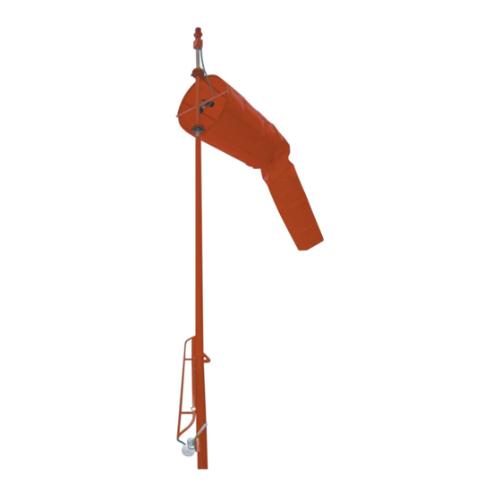
Indicates true direction when wind velocity exceeds 3 knots b. Wind sock full extension when wind velocity exceeds 15 knots 5. Dimensions a. Type L-806 and L-806(L): see Figure 2 b. Type L-807 and L-807(L): see Figure 1 L-807 and L-806 Wind Cone Installation and Maintenance Manual... - Page 12 Specifications With Lighting 246" w/18" basket 264" w/36" basket 214" w/18" basket 18" 232" w/36" 36" basket 192" 77" HBA116 Figure 1. L-807 Dimensions L-807 and L-806 Wind Cone Installation and Maintenance Manual...
-
Page 13: Physical Specifications
Physical Specifications 122" 117” 90” 18" 72" HBA143 Figure 2. L-806 Dimensions L-807 and L-806 Wind Cone Installation and Maintenance Manual... -
Page 14: Getting Started
Getting Started Shipping and Unpacking All components needed for assembly and installation of the L-807, L-807(L), L-806 and L-806(L) are shipped on a standard 10 ft pallet. If additional components or more than one unit is ordered the shipping pallet may be larger. -
Page 15: Taking Inventory
Taking Inventory Taking Inventory Inventory all components prior to installation. Verify that you have everything required to assemble and install the L-807 or L-806 Wind Cone. If there are any missing components contact Hali-Brite ® CAUTION: Always take care in handling individual components to prevent damage or injury. - Page 16 Figure 4. L-806 Wind Cone Components Wind Sock Interior Floodlight Kit consisting of: * Light pole assembly w/obstruction light * 2-light configuration (optional) Exterior Floodlights (optional) Touch-Up Paint Pole 18" Basket Frangible Coupling L-807 and L-806 Wind Cone Installation and Maintenance Manual...
-
Page 17: Tools And Supplies Needed
(Used to tighten nuts to the anchor (Used to set anchor height) bracket) 6. 1-1/16" Open End Wrench 12. 3/16" Allen Hex Wrench (Used to level the anchor nuts) ( to remove electrical access cover plate) L-807 and L-806 Wind Cone Installation and Maintenance Manual... -
Page 18: Installing The L-807 Wind Cone
Installing the L-807 Wind Cone CHAPTER 5 Installing the L-807 Wind Cone In order to simplify the installation of the L-807 wind cone, the process can be broken down into the following subtasks. Perform them in the order they are listed below. -
Page 19: Installing The L-807 Wind Cone Anchor
This ensures that the post will be level when placed onto the anchor. Place a flat washer on top of each of the four 3/4" nuts, see Figure 6. L-807 and L-806 Wind Cone Installation and Maintenance Manual... - Page 20 Installing the L-807 Wind Cone Figure 6. Leveling the Anchor Nuts for the L-807 Wind Cone 1. 3/4" Nut 2. Carpenter Level 3. 3/4" Flat Washer L-807 and L-806 Wind Cone Installation and Maintenance Manual...
- Page 21 Threaded corner post 4. 1/2 in. x 5 ft rebar legs wired to anchor 9. 1/2 inch conduit 2 inches above concrete 5. Concrete Base 7.5 ft deep 10. Threaded corner post L-807 and L-806 Wind Cone Installation and Maintenance Manual...
-
Page 22: Positioning The Swing Arm
Figure 6. The four bottom nuts are used to level the pole. These nuts must be leveled prior to mount- ing the pole, see “Installing the L-807 Wind Cone Anchor” on page 19. L-807 and L-806 Wind Cone Installation and Maintenance Manual... - Page 23 5. Base of Pole 3. 3/4" Lock Washer (4) Crank the top half of the pole to a comfortable working position. Attach the basket to the pole, see the following procedure. L-807 and L-806 Wind Cone Installation and Maintenance Manual...
-
Page 24: Attaching The Basket To The Pole
Attach the lights to the basket, see the following procedure “Installing Lights” on the following page. If the wind cone is unlighted, proceed to “Installing the Wind Sock to the Basket” on page 29. L-807 and L-806 Wind Cone Installation and Maintenance Manual... -
Page 25: Installing Lights
Figure 11, with the slotted end of the light support bracket towards the wind cone lamp. Reinstall the upper bracket bolt and washers and the lower bracket nut and washer, but only finger-tight. L-807 and L-806 Wind Cone Installation and Maintenance Manual... - Page 26 Wire and test the lights, see “Wiring the Lights to the Power Source” on page 28. Install the wind sock, see “Installing the Wind Sock to the Basket” on page 29. L-807 and L-806 Wind Cone Installation and Maintenance Manual...
-
Page 27: Installing The Internal Lighting Kit
Place the two U-bolts around the basket frame and back through the holes in the lightbar, see Figure 13. Tighten the U-bolts to the basket frame. Place anti-locking compound on the basket support pole threads. L-807 and L-806 Wind Cone Installation and Maintenance Manual... -
Page 28: Wiring The Lights To The Power Source
If all lights illuminate and appear to be in working order you can then install the wind sock, see “Installing the Wind Sock to the Basket” on page 29. L-807 and L-806 Wind Cone Installation and Maintenance Manual... -
Page 29: Installing The Wind Sock To The Basket
After the wind sock has been installed, raise the top half of the pole into posi- tion. CAUTION: Disconnect power going to the lights before raising the pole. Using the handcrank on the winch, raise the pole until the hinge is closed, see Figure 15. L-807 and L-806 Wind Cone Installation and Maintenance Manual... - Page 30 Figure 15. Secure the four bolts and nuts. HBA126 Figure 15. Raising the Top Half of the Pole 1. 7/16" Hinge Bolts (4) 2. Swing Arm 3. Winch Handle L-807 and L-806 Wind Cone Installation and Maintenance Manual...
-
Page 31: Installing The L-806 Wind Cone
If external lights are required: continue with “Installing the External Lighting Kit” on page 32. c. If internal lights are required: continue with “Installing the Internal Lighting Kit” on page 33. L-807 and L-806 Wind Cone Installation and Maintenance Manual... -
Page 32: Installing The External Lighting Kit
2. Feed end of cable into top of basket support pipe 3. Place anti-locking compound on threads 4. Pull cable through basket support pipe 5. Pull cable through pole 6. Pull excess cable out bottom of pole L-807 and L-806 Wind Cone Installation and Maintenance Manual... -
Page 33: Installing The Internal Lighting Kit
Install the wind sock, see “Installing the Wind Sock to the Basket” on page 34. HBA123 HBA122 Figure 17. Installing the Internal Lighting Kit 1. U-Bolts 2. 18" Light Bar 3. Internal Floodlights 4. Basket Frame 5. Apply Anti-locking Compound 6. Obstruction Light L-807 and L-806 Wind Cone Installation and Maintenance Manual... -
Page 34: Installing The Wind Sock To The Basket
Inspect the entire assembly for nicks or other damage to painted surfaces. Apply the supplied paint to these areas. Assemble the pole to the baseplate, see “Assembling the Pole to the Base- plate” on page 35. L-807 and L-806 Wind Cone Installation and Maintenance Manual... -
Page 35: Assembling The Pole To The Baseplate
See “Wiring Diagrams” on page 43. If all lights illuminate and appear to be in working order you can then attach the pole to the base can, see the following procedure. L-807 and L-806 Wind Cone Installation and Maintenance Manual... -
Page 36: Attach The Pole Assembly To The Base Can
To attach the completed pole assembly to the base can grasp the pole assembly near the bottom of the basket and stand the pole assembly upright. Move the baseplate on top of the base can and bolt in place. L-807 and L-806 Wind Cone Installation and Maintenance Manual... -
Page 37: Maintaining And Servicing The Wind Cones
Supplies Needed” on page 17. Lowering the Top of the L-807 Pole To perform maintenance on the top half of the L-807 pole you must lower it nearer to the ground. This is done by performing the following steps. -
Page 38: Inspecting Wind Cone Components
Check structure for bird nests or insect Remove from structure. problems. Check for paint damage. Apply touch-up paint as required. Check wind sock for missing cable Replace missing or worn cable straps. straps. L-807 and L-806 Wind Cone Installation and Maintenance Manual... -
Page 39: Replacing Lamps
Internal Flood Light 120 Volt Halogen 100 W, 120 V 2000 hrs External Flood Light 120 Volt Halogen 75W PAR16 2000 hrs NOTE: See Table 6 on page 42 for part number information. L-807 and L-806 Wind Cone Installation and Maintenance Manual... -
Page 40: Replacing An Internal Floodlight Lamp
Unscrew the old lamp and install the replacement. Install the Lamp Housing Cover and tighten the retaining screw. Lamp Housing Cover Retaining Screw HBA156a Figure 22. Replacing 120 VAC External Halogen Lamps L-807 and L-806 Wind Cone Installation and Maintenance Manual... -
Page 41: Replacing An Obstruction Lamp
CAUTION: Do not touch the lamp glass with fingers. Oil on skin may shorten the life of the lamp. Replace the lens. Clasp Clasp HBA142 Figure 23. Removing the Obstruction Light Cover L-807 and L-806 Wind Cone Installation and Maintenance Manual... -
Page 42: Spare Parts
Calling Hali-Brite at 1-800-553-6269. ® • Faxing your order to us at 1-218-546-6854. Recommended Spare Parts TABLE 6. Recommended Spare Parts List for L-806 and L-807 Description Part Number Quantity Lamp, 120 V External Halogen 3400-0122 Lamp, 120 V Internal Halogen... -
Page 43: Wiring Diagrams
CHAPTER 9 Wiring Diagrams The following wiring diagrams are for the internal and external lights on the L-806 or L-807 Wind Cone. Refer to the following table to locate the correct figure. Sock Diameter Type Light Type Power Wiring Diagram L-806 18"... - Page 44 HBA137 116 W, 120 VAC Obstruction Lamp 100 W, 120 VAC Lamps HBA139 Figure 24. 120 VAC 36" Internal Halogen Wind Cone Light L-807 and L-806 Wind Cone Installation and Maintenance Manual...
- Page 45 HBA135 116 W, 120 VAC Obstruction Lamp 100 W, 120 VAC Lamps HBA140 Figure 25. 120 VAC 18" Internal Halogen Wind Cone Light L-807 and L-806 Wind Cone Installation and Maintenance Manual...
- Page 46 75W 120V 116W 120V Lamp Lamp OB HBA135r2 116 W, 120 VAC Obstruction Lamp 75 W, 120 VAC Lamp HBA141r2 Figure 26. 120 VAC 18" or 36" External Halogen Light L-807 and L-806 Wind Cone Installation and Maintenance Manual...
- Page 47 Figure 27. 12 VDC External and Internal LED Light L-807 and L-806 Wind Cone Installation and Maintenance Manual...
- Page 48 COUPLING WHITE BLACK 120V or 230V NEUTRAL 120Vor 230V PHASE WHITE BLACK MOV (120V ONLY) OBSTRUCTION GREEN LIGHT WINDSOCK LAMP Figure 28. 120VAC and 230VAC 18” and 36” External LED Light L-807 and L-806 Wind Cone Installation and Maintenance Manual...
- Page 49 WINDSOCK OBSTRUCTION LIGHT LAMP LAMP WHITE BLACK ROTATING COUPLING WHITE BLACK PHASE NEUTRAL BLACK WHITE GREEN OBSTRUCTION LIGHT WINDSOCK LAMPS Figure 29. 120 or 230 VAC 18” Internal LED Light L-807 and L-806 Wind Cone Installation and Maintenance Manual...
- Page 50 WINDSOCK OBSTRUCTION LIGHT LAMP LAMP LAMP WHITE BLACK ROTATING COUPLING WHITE BLACK PHASE NEUTRAL BLACK WHITE GREEN OBSTRUCTION LIGHT WINDSOCK LAMPS Figure 30. 120 or 230 VAC 36” Internal LED Light L-807 and L-806 Wind Cone Installation and Maintenance Manual...
- Page 51 LAMP LAMP WHITE BLACK ROTATING COUPLING WHITE BLACK OBSTRUCTION LIGHT TO 6.6AMP TRANSFORMER WINDSOCK LAMP Figure 31. 6.6 Amp 18” and 36” External and Internal LED Wiring (Internal fixture not shown.) L-807 and L-806 Wind Cone Installation and Maintenance Manual...
Need help?
Do you have a question about the L-807 and is the answer not in the manual?
Questions and answers