Table of Contents
Advertisement
Quick Links
Advertisement
Table of Contents

Summary of Contents for Aaeon AEC-206
- Page 1 AEC-206 Wallmount Chassis Part No. 2007206010 V.1 Printed in Taiwan 1/ 2003...
- Page 2 AAEON, assumes no liabilities resulting from errors or omissions in this document, or from the use of the information contained herein. AAEON reserves the right to make changes in the product design without notice to its users.
-
Page 3: Table Of Contents
W a l l m o u n t C h a s s i s A E C - 2 0 6 Contents Chapter 1 General Information 1.1 Introduction..................1-2 1.2 Features....................1-3 1.3 Specifications..................1-3 1.4 Dimension Diagram................1-4 1.5 Connector and Drive Bay Location Diagram........ 1-5 Chapter 2 Quick Installation Guide 2.1 Removing the cover................2-2 2.2 Adding a floppy drive.................2-3... -
Page 4: Chapter 1 General Information
Wallmount Chassis A E C - 2 0 6 Chapter General Information 1- 1 Chapter 1 General Information... -
Page 5: Introduction
The AEC-206 comes with a 6-slots PICMG or an ISA back-plane to maximize the high performance of Pentium 4 full-size CPU Card. An ATX 12V power supply up to 300W is also equipped dedicated to Pentium 4 CPU Card. -
Page 6: Features
Wallmount Chassis A E C - 2 0 6 1.2 Features • Supports high performance Full-Size CPU Cards • Supports 6-slot PICMG bus passive backplanes • Supports wallmount or desktop applications • Supports one front access 5.25” CD-ROM, one 3.5” FDD and two 3.5”... - Page 7 Wallmount Chassis A E C - 2 0 6 • Net weight (Bare): 7.8 kg (17 lbs) • Color: Black • Operating temperature: 5-95%@40C, non-condensing • Storage humidity: 5-95% Passive Backplane Options Backplane Slots per S egment Segment Model No. (PISA/PCI/ISA/PICMG) (Systems) BP206SI-V60...
-
Page 8: Dimension Diagram
W a l l m o u n t C h a s s i s A E C - 2 0 6 1.4 Dimension Diagram Chapter 1 General Information 1 - 5... -
Page 9: Connector And Drive Bay Location Diagram
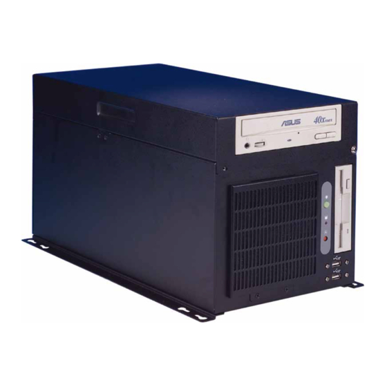
Wallmount Chassis A E C - 2 0 6 1.5 Connectors and Drive Bay Location Diagram 1. Two internal 3.5” hard disk bay 2. 5.25” CD-ROM drive 3. Floppy drive 4. Two USB ports 5. Power ON/OFF Switch and LED, HDD LED, Reset Switch. 6. - Page 10 Wallmount Chassis A E C - 2 0 6 8. COM port 9. Parallel port 10. LVDS Interface 11. Hot-Air outlet 12. Power supply Chapter 1 General Information 1 - 7...
-
Page 11: Chapter 2 Quick Installation Guide
W a l l m o u n t C h a s s i s A E C - 2 0 6 Chapter Quick Installation Guide Chapter 2 Quick Installation Guide... -
Page 12: Removing The Cover
W a l l m o u n t C h a s s i s A E C - 2 0 6 2.1 Removing the cover Before you install any drives or plug-in cards into AEC-206, you have to open the cover and remove the hold-down bar first. Unscrew the cover, lift the lid and keep the top of the chassis open. -
Page 13: Adding A Floppy Drive
W a l l m o u n t C h a s s i s A E C - 2 0 6 2.2 Adding a Floppy Drive To install a floppy drive, please refer to the following charts and procedures. - Page 14 W a l l m o u n t C h a s s i s A E C - 2 0 6 Attach the mounting bracket with the FDD inside to the chassis with four screws. Chapter 2 Quick Installation Guide 2 - 4...
-
Page 15: Adding A Cd-Rom Drive
W a l l m o u n t C h a s s i s A E C - 2 0 6 2.3 Adding a CD-ROM Drive To install a CD-ROM drive, please refer to the following charts and procedures. -
Page 16: Adding A Hard Disk Drive
W a l l m o u n t C h a s s i s A E C - 2 0 6 2.4 Adding a Hard Disk Drive To install a hard disk drive, please refer to the following charts and procedures. -
Page 17: Adding The Hold Down Bar
W a l l m o u n t C h a s s i s A E C - 2 0 6 2.5 Adding the hold-down bar After you assemble all the drives, plug-in cards and cables inside the chassis, be sure to put the hold-down bar back to strength its anti-vibration ability. -
Page 18: Replacing The Filter
W a l l m o u n t C h a s s i s A E C - 2 0 6 2.6 Replacing the filter You may need to replace the used filter after a period of time. Please refer to the following charts and procedures. -
Page 19: Adding The Wallmount Kit
W a l l m o u n t C h a s s i s A E C - 2 0 6 2.7 Adding the wallmount kit You can easily mount AEC-206 onto wall with the supplied wallmount kit. Turn over the chassis to expose its bottom upward. -
Page 20: Appendix Front Panel Daughter Board And Backplanes
W a l l m o u n t C h a s s i s A E C - 2 0 6 Appendix Front panel daughter board and Backplane Appendix A Front panel daughter board and Backplane... -
Page 21: Front Panel Daughter Board Mechanical Drawing
W a l l m o u n t C h a s s i s A E C - 2 0 6 A.1 Front panel daughter board Mechanical Drawing A.2 Front panel daughter board Jumpers & Connectors The board has a number of jumper and connectors that allow you to configure your system to suit your application. -
Page 22: Backplane
PWRLED+ ( ATX Mode ) PWRLED- ( ATX Mode ) IDELED+ IDELED- RESETSW_P1 RESETSW_P2 A.3 Backplane AEC-206 comes with one backplane for expansion. You can select either BP206SI-V60 or BP206SG-P3-V61 based on your application. Backplane Slots per Segment Segment Model No. (PISA/PCI/ISA/PICMG) - Page 23 W a l l m o u n t C h a s s i s A E C - 2 0 6 BP206SG-P3-V61 Unit: mm Appendix A Front panel daughtr board and Backplane...
Need help?
Do you have a question about the AEC-206 and is the answer not in the manual?
Questions and answers