
Subscribe to Our Youtube Channel
Summary of Contents for Neurosoft Neuro-ERG/V
- Page 1 Technical Manual Neuro-ERG/V Veterinary Digital ERG System TM006.04.001.000 (14.06.2019)
- Page 2 Neurosoft © 2020 5, Voronin str., Ivanovo, 153032, Russia P.O. Box 10, Ivanovo, 153000, Russia Phone: +7 (4932) 24-04-34; +7 (4932) 95-99-99 Fax: +7 (4932) 24-04-35 E-mail: info@neurosoft.com Internet: www.neurosoft.com...
-
Page 3: Table Of Contents
Contents Introduction ....................... 4 Important Safety Instructions .................. 5 Intended Use ....................... 5 General Description ..................... 5 Contraindications ....................6 Possible Side Effects ................... 6 Description ......................7 1.1. Main Specifications ..................7 1.2. Principle of Operation ................. 10 1.3. Connectors and Indicators ................12 1.4. -
Page 4: Introduction
Introduction This technical manual (hereinafter referred to as "the manual") is the combined docu- ment describing operation and maintenance of the Neuro-ERG/V veterinary digital ERG system (hereinafter referred to as "the system"). The document certifies technical parameters of the system, which are guaranteed by the manufacturer. -
Page 5: Important Safety Instructions
Important Safety Instructions Important Safety Instructions Intended Use The Neuro-ERG/V system is intended to perform electroretinography (ERG) tests and studies of flash visual evoked potentials (FVEPs). The system can be used in veterinary hospitals and experimental laboratories of re- search institutions to study: ... -
Page 6: Contraindications
Neuro-ERG/V (Technical Manual) Electroretinography (ERG); Generation of examination report; Review, storage and printing of the recorded curves, results of their analysis and examination reports. Contraindications The electroretinography (ERG) is not recommended if the examined animal has: signs of acute inflammatory and/or allergic disease of cornea, conjunctiva, eyelid, or traumatic injury of eyeball;... -
Page 7: Description
Description Description 1.1. Main Specifications Table 1. Main Specifications Parameters Values Amplifier Channels Number of channels 200 Hz – 40 (160) kHz Sampling rate 20 µV 50 mV Voltage range Ratio error of voltage measurement: in the band from 20 up to 100 µV ±15% ... - Page 8 Neuro-ERG/V (Technical Manual) Table 1. Continued Parameters Values Visual Stimulator Maximum brightness of: (1100 ± 110) cd/m LED goggles (1500 ± 150) cd/m mini-ganzfeld stimulator Maximum brightness power of: white penlight (0.2 ± 0.05) cd (0.3 ± 0.075) cd red penlight ...
- Page 9 Description Table 1. Continued Parameters Values Operation Conditions +10 up to +35°C Temperature Humidity from 30 to 85% non-condensing Atmospheric pressure 70-106 kPa Safety and Electromagnetic Compatibility Electromagnetic compatibility (EMC) is provided by conformance to IEC 60601-1-2- 2014 (EN 60601-1-2:2015) requirements. The system is intended for operation in electromagnetic environment, which special features are specified in Annex 2.
-
Page 10: Principle Of Operation
Neuro-ERG/V (Technical Manual) 1.2. Principle of Operation The operation of the system is based on the recording and input of biopotentials to computer to perform the analysis of their electrical activity, including the response to stimulus. The block diagram of the system is shown in Fig. 1. - Page 11 Description sound stimulator in a discrete form, which is transformed by the digital-analog con- verter to the analog form, amplified by the sound amplifier and is supplied to the audi- tory stimulator. DSP also generates the visual signal which is transferred to the visual stimulator via the visual amplifier.
-
Page 12: Connectors And Indicators
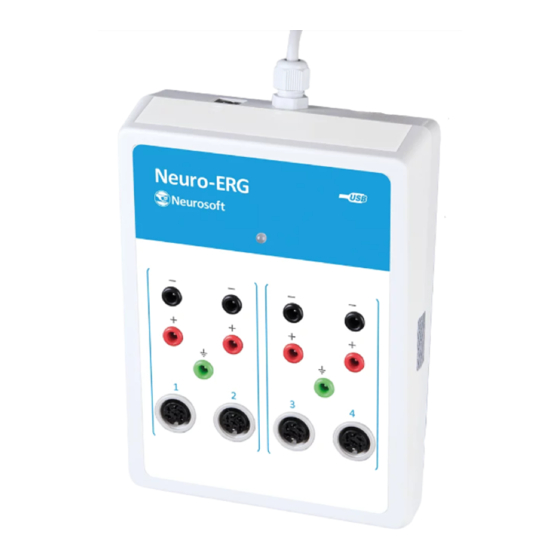
Neuro-ERG/V (Technical Manual) 1.3. Connectors and Indicators The front and side panels of the amplifier unit are shown in Fig. 2 and Fig. 3. On the front panel of the amplifier unit there are the touch-proof and DIN-connectors to attach the electrodes and operation indicator (Fig. 2). The channel numbers are marked with Arabic figures “1”, “2”, “3”... - Page 13 Description On the top side panel of the amplifier unit there are USB cable for connection to PC and the trigger input socket to connect the stimulators of third-party manufacturers (Fig. 3). Fig. 3. Side panel of amplifier unit. The front and rear panels of auditory-visual stimulator unit are shown in Fig. 4 and Fig.
-
Page 14: Synchronization With Stimulators Of Third-Party Manufacturers
Neuro-ERG/V (Technical Manual) On the rear panel of the auditory-visual stimulator unit there are the connector for USB cable (for connection to PC), connector for reversal pattern monitor (not for vet- erinary use) and trigger output socket (Fig. 5). Fig. 5. The rear panel of the auditory-visual stimulator unit. -
Page 15: Synchronization With Neuro-Mep.net Software
Description Table 2. Functions of socket pins. Pin number Name Function +SYNC Trigger signal input Common For the synchronization, apply positive TTL pulse on the + SYNC output in relation to 0 V (Fig. 7). The synchronization will occur by the pulse front with ±25 µs accuracy. Fig. - Page 16 Neuro-ERG/V (Technical Manual) Fig. 8. The acquisition start window from external stimulator. In the stimulation settings it is recommended to set those stimulus parameters which the external stimulator has as these particular values are saved together with the trace and taken into analysis.
-
Page 17: Labeling
Description The Third-party firm stimulator check box (Fig. 8) is NOT checked! In other aspects the signal acquisition does not differ from the one described in the corresponding chapters of the user manual. 1.6. Labeling The example of labeling of electronic units is shown in Fig. 9. Fig. - Page 18 Neuro-ERG/V (Technical Manual) The equipment is identified with the GS1-128 barcode integrated to the barcode in DataMatrix format (Fig. 10). Fig. 10. DataMatrix barcode. Data Matrix is a two-dimensional matrix barcode, consisting of black and white “cells” or modules of different brightness arranged in either a square or rectangular pattern.
-
Page 19: Assembly And Installation
Assembly and Installation Assembly and Installation 2.1. Requirements to Personnel The assembly and installation of the system should be carried out by a person who is empowered by the manufacturer or technical personnel of the medical institution which is going to use it. Remember, that the accuracy of system mounting defines the safety and quality of its operation. - Page 20 Neuro-ERG/V (Technical Manual) protective ground of the multi-socket electric mains extender can lead to summation of leakage current in all connected units on their metal parts to dangerous values. Before the system setting, the electrician must check the quality of standard tripolar sockets and the integrity of the protective ground circuit.
- Page 21 Assembly and Installation Fig. 12. Placement of equipment connected to notebook PC. As a power unit, the notebook PC power unit corresponding to IEC 60601-1:2012 (AAMI/ANSI ES 60601-1:2005/(R2012) and A1:2012 and A2:2010/(R)2012, EN 60601-1:2006/A1:2013) is used. As for isolation transformer, the isolation transformer ТМ-630М...
-
Page 22: Unpacking And Check Of Delivery Set
If the distributive is missing or the software update is required, address to your local dealer. The authorized Neurosoft dealers are listed on the web- site: https://neurosoft.com/en/pages/dealers. The system consists of several units. Each of them is attached to USB connector of PC. - Page 23 Assembly and Installation Fig. 13. Connection of system to computer. If the mini-ganzfeld stimulator is included in the delivery set, it is connected to the au- ditory-visual stimulator via the connector used for the visual stimulator (LED goggles) (Fig. 14). The bracket assembly for mounting the mini-ganzfeld stimulator and LED penlights is shown in Fig.
-
Page 24: Proper Use
Neuro-ERG/V (Technical Manual) Proper use 3.1. Safety Measures To provide safety measures and exclude the possibility of electric trauma of medical staff or examined animal, it is PROHIBITED: to use the system which mounting and setting was done incorrectly without follow- ing the manual instructions;... -
Page 25: Troubleshooting
Trouble Cause Way of Removal The program message: The amplifier is not connected Check whether the amplifier is “Neurosoft systems supported to the computer. connected. If there are no by the software can’t be connection errors, disconnect found”. the amplifier from the computer and connect it again in several seconds. - Page 26 Neuro-ERG/V (Technical Manual) Table 3. Continued Trouble Cause Way of Removal The program message: The other program using the Close the running program “Neuro-ERG auditory-visual stimulator is opened (for that is using the stimulator. If you can’t find such a program,...
- Page 27 Proper use Table 3. Continued Trouble Symptom Cause Way of Removal High electromagnetic The electrodes not used at Disconnect the electrodes not interference in the recorded the moment are connected to used at the moment from the signal (frequency – 50 Hz or amplifier (i.e.
-
Page 28: Getting Started
Neuro-ERG/V (Technical Manual) 3.4. Getting Started Before you perform the exams using this system, set up the system and other equip- ment according to the user manual, depending on the type of examination. The examination includes the following stages: placement of electrodes and sensors;... -
Page 29: Maintenance
4.3. Disinfection Before cleaning the electronic unit, switch it off. As you clean, visually inspect the unit and its components for damage or wear. Contact Neurosoft if you notice damage to the exterior of the component. For routine cleaning of the electronic unit, use a cloth gently wrung in phenoles (Bacil- lotex®... -
Page 30: Current Repair
Neuro-ERG/V (Technical Manual) gen peroxide solution). The use of organic solvents and aromatic oils must be avoid- ed. Never submerge the device or the cables in disinfectant or other liquids. After testing the electrodes should be removed from the examined animal immediate- ly. -
Page 31: Led Goggles
Current Repair Fig. 15. Electrical schematic of computer interface cable. 5.4. LED Goggles The LED goggles are examined for external signs of cable damage. The check of the circuits from the connector side is performed according to the schematic shown in Fig. -
Page 32: Led Penlights
Neuro-ERG/V (Technical Manual) 5.5. LED Penlights The LED penlights are examined for external signs of cable damage. The check of the circuits from the connector side is performed according to the schematic shown in Fig. 17. The check is done using the device designed to test the diodes. Disassemble the housing of the cable connector and inspect the montage. -
Page 33: Disposal
Silver content, g Corneal hook electrode (NS006106.004) 0.21 Delivery Set and Package Data The Neuro-ERG/V veterinary digital ERG system is collected and packed. The system is ready for operation. Package report number ________________ Package report date ___________________ The detailed information about the delivery set is described in the package report... -
Page 34: Warranty
9.4. The manufacturer is obliged to repair the system in case of its breakdown during the warranty period free of charge. The repair is carried out in Neurosoft service cen- ter (5, Voronin str., Ivanovo, 153032, Russia) in compliance with the procedure stated in chapter 10 “Reclamation”. -
Page 35: Reclamation
10.1. In case of system breakdown or faultiness in the period of warranty and also product defect detected when primary acceptance, the consumer should send written notification to Neurosoft. This notification should contain the following information: customer’s name and address;... -
Page 36: Annex 1. Delivery Set
Annex 1. Delivery Set The amplifier, auditory-visual stimulator, footswitch, dedicated keyboard and software are included in the delivery set of the Neuro-ERG/V system. The mentioned compo- nents of the system as well as other components and bought articles can be delivered to the customer both jointly and separately. - Page 37 220/230 V, 10 A, L, Power cable IEC C14-Schuko type F socket not more than 1 m (3G×0,75 sq. mm) Technical manual for TM-630 TM036.03.001.000 Package NS036901.001 Operational Documentation: Neuro-ERG/V technical manual TM006.04.001.000 Neuro-MEP.NET/V user manual UM006.04.002.000 Package: Package NS002901.001 Package NS002901.002...
-
Page 38: Annex 2. Electromagnetic Emissions And Immunity
Neuro-ERG/V (Technical Manual) Annex 2. Electromagnetic Emissions and Immunity Guidance and manufacturer’s declaration – electromagnetic emissions The system is intended for use in the electromagnetic environment specified below. The customer or the user of the system should assure that it is used in such an environment. - Page 39 Annex 2. Electromagnetic Emissions and Immunity Guidance and manufacturer’s declaration – electromagnetic immunity The system is intended for use in the electromagnetic environment specified below. The customer or the user of the system should assure that it is used in such an environment. IEC 60601 test Electromagnetic Immunity test...
- Page 40 Neuro-ERG/V (Technical Manual) Guidance and manufacturer’s declaration – noise immunity The system is intended for operation in electromagnetic conditions environment described below. The customer or user of the system should provide the system operation in the specified electromagnet- ic conditions environment.
- Page 41 Annex 2. Electromagnetic Emissions and Immunity Recommended separation distances between portable and mobile RF communications equipment and the system The system is intended for use in an electromagnetic environment in which radiated RF disturbances are controlled. The customer or the user of the system can help prevent electromagnetic interference by maintaining a minimum distance between portable and mobile RF communications equipment (transmitters) and the system as recommended below, according to the maximum output power of the communications equipment.
Need help?
Do you have a question about the Neuro-ERG/V and is the answer not in the manual?
Questions and answers