
Related Manuals for TC FLUID CONTROL KMS-2

Summary of Contents for TC FLUID CONTROL KMS-2
- Page 1 Installation and operating manual KMS-2 Magnetostrictive Level Transmitter Please retain for future use Revision H File Exd kms-2 iom revH.doc...
-
Page 2: Table Of Contents
INDEX Symbols Used …………………….………………………………………1 Safety Information …………………………………………………………………….1 Introduction and Scope of use …………………………………………….2 Output signals ……………………………………………………….…….2 Installation …………………………………………………………….……………….3 Magnetic Level Gauge Application …………………….……………….4 Immersion Application …………………………………….……………….5 Electrical Connections …………………………………………………………….6 Connection Cable Selection …………………………………………………….6 Adjustment and Configuration …………………………………………………….7 Painting and coatings ………………………………………………………………..9 Certification …………………………………………………………………………….10 Special Conditions for Safe Use ……………………………………………………...10... -
Page 3: Symbols Used
EC type examination certificate. Information Facts and information concerning proper operation of the KMS-2 Level Transmitters Instructions for electrical installation Information on proper electrical installation. Safety information Read these instructions before installation and putting into operation. -
Page 4: Output Signals
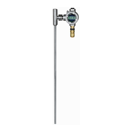
Installation and Operating Manual INTRODUCTION The KMS-2 transmitter is a 4 to 20 mA loop powered transducer for measuring the level of liquid in a vessel either directly (immersion application) using an annular float, or indirectly by mounting on a magnetic level gauge. - Page 5 ATEX KMS-2/Exia/Exd Transmitter Installation and Operating Manual INSTALLATION GENERAL. Magnetic Level Gauge Applications The unit should be fitted to the level gauge with reference to Fig1 using the mounting clips and insulation (if required) supplied. The unit should be positioned such that the XXXX marks around the circumference align with the upper and lower vessel connection points.
- Page 6 ATEX KMS-2/Exia/Exd Transmitter Installation and Operating Manual TOP MOUNTED HEADSHELL UNIT TOP SIDE MOUNT SECTION SHOWING TYPICAL TRANSMITTER MOUNTING ARRANGEMENT. KLINGER RED WAFERS IN BOX INDICATE DAMAGED FLOAT. BOTTOM SIDE MOUNT Fig 1 Page 4 of 16 KMS-2:Exia/Exd IOM Rev H...
-
Page 7: Immersion Application
ATEX KMS-2/Exia/Exd Transmitter Installation and Operating Manual Typical Installation When Fitted to Magnetic Level Gauge For Zone 0 areas, refer to the section covering ‘Special Conditions For Safe Use’ under Certification. Fig 2 Immersion Application Ensure that the PFA/PTFE washer is correctly fitted to prevent the risk of sparking if the float was to hit the stop. -
Page 8: Electrical Connections
ATEX KMS-2/Exia/Exd Transmitter Installation and Operating Manual ELECTRICAL CONNECTION Unscrew the lid to gain access to the rear terminal enclosure; the terminal block can then be removed to facilitate connections. Select the correct cable entry point dependent on the orientation of the sensor. The connection cable should be bought in through an M20 gland suitable to maintain the required IP rating, and then connected to the + and –... -
Page 9: Adjustment And Configuration
ATEX KMS-2/Exia/Exd Transmitter Installation and Operating Manual 28V dc K&TC PCB620 REV D Fig 3 Cable entry via M20 gland Fig 4 Connection Details Adjustment and Configuration: The unit is normally set at the factory to the required specification •... - Page 10 ATEX KMS-2/Exia/Exd Transmitter Installation and Operating Manual 9. Press the ‘Span’ button until the ‘Span’ LED stays on 10. Wait until the ‘Span’ LED extinguishes. (output 20mA) If the optional LCD is fitted the display will read ‘CAL’ during the setting process.
- Page 11 ATEX KMS-2/Exia/Exd Transmitter Installation and Operating Manual normal operation either depress the opposite button or cycle the power. Coatings and painting. The maximum non-conductive coating thickness allowed for the transmitter housing is limited to 200 microns. All coated Exd units must be earthed accordingly, an external earth post is provided.
-
Page 12: Certification
ATEX KMS-2/Exia/Exd Transmitter Installation and Operating Manual In accordance to EC council directive 89/336/EEC Emissions EN 61326:2004 (Class B) STANDARD DESCRIPTION PORT RESULT EN 61326 Radiated Emissions Enclosure Pass EN 61326 Conducted Emissions Not applicable Not Tested Immunity tests to EN 61326: 2004 A1, A2, and A3... -
Page 13: Fault Analysis Sheet
ATEX KMS-2/Exia/Exd Transmitter Installation and Operating Manual tanks etc. (EPL Ga), the probe shall be installed in accordance with IEC 60079-26, [i.e. in a separate ventilated pocket and/or fed from an I.S. supply]. FAULT ANALYSIS SHEET Problem Possible Fault Action... -
Page 14: Technical Data
ATEX KMS-2/Exia/Exd Transmitter Installation and Operating Manual TECHNICAL DATA Materials Measuring probe: - 316L Housing: - Epoxy coated aluminium or 316L Stainless steel Cable entry Thread Size: - M20x1.5mm Connection conductor size: - 0.5mm² - 2.5mm² Supply voltage (Nominal 24VDC) - Page 15 ATEX KMS-2/Exia/Exd Transmitter Installation and Operating Manual Where ambient conditions are outside this range additional insulation or shielding will be required please consult sales office Page 13 of 16 KMS-2:Exia/Exd IOM Rev H 18/05/10...
- Page 16 TC FLUID CONTROL LTD UNIT 4 THE INTERCHANGE WESTED ROAD SWANLEY KENT BR8 8TE TEL ++44(0) 1322 622400 FAX ++44(0) 1322 660621 E-mail instruments@tc-fluidcontrol.com...
Need help?
Do you have a question about the KMS-2 and is the answer not in the manual?
Questions and answers