Table of Contents
Advertisement
Quick Links
Advertisement
Table of Contents

Summary of Contents for mattke MDCA Series
- Page 1 Precision Servodrive for DC motors...
-
Page 3: Table Of Contents
Index Chapter 1 1.1 Safety and note ........................4 1.2 Operation mode and feedback ..................5 1.3 Model and size ........................6 1.4 View product ........................7 1.5 Ambient conditions ......................8 1.6 Ventilation ........................... 8-9 1.7 Dimensions .......................... 9 Chapter 2 2.0 Signals input and output ....................10-11 2.1 Fault output .........................12... - Page 4 MDCA XXX/XX...
-
Page 5: Safety And Note
1.1 Safety and note Caution Users must keep well clear in mind that this motion control equipment is capable of producing Users must keep well clear in mind that this motion control equipment is capable of producing high high forces and rapid movement so they must be used with attention especially during the forces and rapid movement so they must be used with attention especially during the application application program’s development. -
Page 6: Operation Mode And Feedback
1.2 Operation mode and feedback Description This is a drive capable to drive DC brush motors, up to 3Nm. It‘s a High Performance full four quadrant drive servo amplifier. The mosfet output power stage is controlled by a 20 Khz PWM (Pulse Width Modulation) signal that allows it to drive servo motors where high dynamic per- formance and precise speed is required. -
Page 7: Model And Size
1.3 Model and size Model available POWER SUPPLY Model 12 8 - 28 Vdc* 14Vdc** Model 65 20 - 84 Vdc* 60Vdc ** Model 100 30 - 130 Vdc* 100Vdc ** Model 130 35 - 165 Vdc* 130Vdc ** * min/max power supply **Typical The power supply voltage has to be a transformer-isolated voltage. -
Page 8: View Product
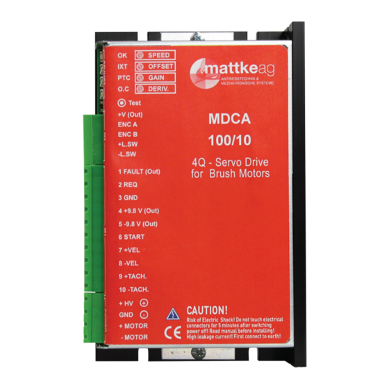
1.4 View product (1) Product Label Product Label (2) Fixing screw Fixing screw (3) Product Cover Product Cover (4) Solder bridges Solder bridges (5) Adjustement zone Adjustement zone (6) Four calibration Potentiometers (7) Four Leds Four calibration Potentiometers (8) TEST point (Encoder, Tacho or Armature velocity) Four Leds... -
Page 9: Ambient Conditions
1.5 Ambient conditions Cable duct Dimensions are expressed in millimeters. 5,3" Conductive mounting panel (zinc coated) Cable duct Positioning in the electrical box Follow the instructions in the positioning of the servodrive in the electrical box. Follow the instructions in the positioning of the servodrive in the electrical box. -
Page 10: Dimensions
SIZE MODEL 7/14 10/20 N = Standard radiator (operating ambient temperature from 0 to 40°C) V = Standard radiator + supplementary ventilation (operating ambient temperature from 0 to 45°C) N.A = Not available ... -
Page 11: Signals Input And Output
2.0 Signals input and output The figure below shows the view of the converter terminals. M1 Signal terminal 10 pins „type GMST 2,5/10-G-5,08“ M2 Signal terminal 5 pins „type MC 1,5/5-ST-3,81“ POWER Terminals 4 pins „type GMST 2,5/4-G-5,08“ On the test point „TEST“ you can see the signal of velocity speed. The output from 0 to + /-8V is from zero to maximum speed. -
Page 12: Fault Output
2.1 FAULT output (M1 signal terminal pin 1) Fault drive, open collector output max. 50mA Fault drive, open collector output max. 50mA Normally closed, opens when the drive in protection mode Normally closed, opens when the drive in protection mode Fault drive, open collector output max. -
Page 13: Ausiliary Power Supply +/-9.8V
Current output limitation With an external potentiometer connected from GND and REQ input, you have a limitation of With an external potentiometer connected from GND and REQ input, you have a limitation of output output current (from zero to max. size) drive‘s. current (from zero to max. -
Page 14: Start Input
2.5 Start input (M1 signal terminal pin 6) The standard drive is furnished in this configuration. The standard drive is furnished in this configuration. Start enable input has logic range: >+9V to +30Vdc (min/max) Start enable input has logic range: >+9V to +30Vdc (min/max) ... -
Page 15: Tachogenerator Input
Speed reference from external potentiometer The following figure shows an application with speed reference connections using an internal +/-9.8V power supply. The speed potentiometer must have an included value between >5 and <10Kohm. The following figure shows an application with speed reference connections using an internal +/-9.8V power supply. -
Page 16: Ausiliary Power Supply +V
2.8 Ausiliary power supply +V (out) (M2 signal terminal pin 1) On the terminal (+V) is available auxiliary power supply voltage +5V (+12 V on request order). This output can be used to power the encoder on the motor. The capacity of the output current is 130mA max. - Page 17 corresponding direction. Note: - This Drive is factory set with the SG and SH solder bridge close - DON'T connect any voltage in the +L.SW and -L.SW inputs if the soldiering point SG and SH are closed - When one of these said contacts is intercepted the motor stops with the required inertia. Fig.
-
Page 18: Power Supply Construction
3.0 Power supply construction Normally the power supply is built by a transformer, a bridge rectifier and a filter capacity. Alternatively, the power supply can also be of switching type, in this case refer factory by the Normally the power supply is built by a transformer, a bridge rectifier and a filter capacity. - Page 19 Voltage motor If the secondary voltage of power supply is VDC, the Vdc motor is calculated by the formula: VDC = Vdc motor / 0,85 Where the Vdc motor is a sum of FCEM + the drop R*I for the winding resistance motor ...
-
Page 20: Connections To Earth And Ground
Secondary of the transformer: Use the table below FUSE F2 (A) SIZE Drive (A) 7/14 10/20 3.1 Connections to earth and ground Make sure that the servodrive and the motor are connected to earth in accordance with the Make sure that the servodrive and the motor are connected to earth in accordance with the current current norms. -
Page 21: Note About Connections
3.2 Note about connections Multiple connection In the case of multiple servodrives on the same power supply, make connections-type stars, see drawing back. Connect also feed converters using the shortest cable possible. If the cable length In the case of multiple servodrives on the same power supply, make connections-type stars, exceeds 2m, twist the + and - leads together as twisted pairs. -
Page 22: Internal Adjustements
4.0 Internal adjustements The adjustments are located inside the converter. All calibration pins are mount on headers The adjustments are located inside the converter. All calibration pins are mount on headers spaced. It ‘better to use a resistors with 1/4 watt (10,16mm) pitch and the capacitors (5.08mm) spaced. - Page 23 4.1 Brush motor with encoder feedback The following diagram shows an tipical application utilizing a Dc One with Brush motor. The + M and -M output are identified on the POWER connector of the product. The following diagram shows an tipical application utilizing a Dc One with Brush motor.
- Page 24 Setting for Brush motor with encoder feedback In this configuration, the drive must set with the following Solder bridges and below internal setting: In this configuration, the drive must set with the following Solder bridges and below internal setting: SOLDER BRIDGES ADJUSTEMENT ZONE...
- Page 25 4.2 Brush motor with tachogenerator The following diagram shows an tipical application utilizing a Dc One with Brush motor. The The following diagram shows an tipical application utilizing a Dc One with Brush motor. The speed loop velocity is by tachogenerator feedback.
- Page 26 Setting for Brush motor with tachogenerator In this configuration, the drive must set with the following solder bridges and below internal set- In this configuration, the drive must set with the following solder bridges and below internal setting: ting: SOLDER BRIDGES ADJUSTEMENT ZONE...
- Page 27 4.3 Brush motor in armature feedback The following diagram shows an tipical application utilizing a Dc One with Brush motor. The The following diagram shows an tipical application utilizing a Dc One with Brush motor. The speed loop velocity is by internal armature feedback.
- Page 28 Setting for Brush motor with armature In this configuration, the drive must set with the following solder bridges and below internal In this configuration, the drive must set with the following solder bridges and below internal setting: setting: SOLDER BRIDGES ADJUSTEMENT ZONE...
-
Page 29: Current Adjustments
Setting for Brush motor with armature (Continue) RCA resistor calculations Insert an RCA resistor on the header (ajustement zone) to compensate for voltage loss due to motor resistance reducing the loss of RPM. The formula is as follows: RCA (Kohm) = 0,49 * 1000 * Vmot Vref * Ipk * Ri Where: Vmot= Nominal voltage of the motor. -
Page 30: Ramp Time Adjustments
RIP resistor (Peak current adjustment) RIP resistance limits the maximum current supplied by the converter. For the calculation see the following table: Value of RIP in Kohm Rip value 6,48 7/14 12,2 11,3 10,5 10/20 20 18,5 17,5 16,2 14,1 13,2 12,5 10,7 10... -
Page 31: Potentiometer Adjustments
Ramp enabled +3,3V MOTOR The time shown on the right are related to a change to step on the reference signal input Table: + /-VEL of 10V. The time shown on the right are Resistance (ohm) TIME (sec) related to a change to step on the 27 Ohm Resistance (ohm) -
Page 32: Dynamic Adjustments
FUNKTION SPEED Motor fine speed calibration. With rotating clockwise (CW) or counterclockwise (CCW) is possible increase / decrease the speed of the motor with range + / -25% OFFSET Offset adjustment. Allows the balance to zero motor speed. Adjust this potentiometer to cancel any motor speed offset when the Velocity input is zero. - Page 33 The multi-turn GAIN and DERIV trimmer allow to dynamically tune of the motor and its mechanics linked to it. These trimmers have full excursion from minimum to maximum, with 15 turns of rotation of the same. The charts shown the track 1 "yellow" is the speed signal available in the point TEST. Track 2 blue highlights instead the current signal.
-
Page 34: Indicator Leds And Protections
4.8 Indicator Leds and protections The protections are all displayed by five LEDs on the front of the drive. It also comes with The protections are all displayed by five LEDs on the front of the drive. It also comes with a series of a series of protections designed to safeguard in case of malfunction, the drive and the motor. - Page 35 Hier ist Platz für Ihre Notizen: Mattke AG Tel.: +49 (0)761 / 15 23 4 - 0 Leinenweberstraße 12 Fax.: +49 (0)761 / 15 23 4 - 56 D-79108 Freiburg info@mattke.de . www.mattke.de...
- Page 36 V 1.0...
Need help?
Do you have a question about the MDCA Series and is the answer not in the manual?
Questions and answers