
Related Manuals for Emakefun PS2X

Summary of Contents for Emakefun PS2X
- Page 1 PS2X&Motor Drive Board Instruction Manual V.1.2 Copy right © 2018 Shenzhen Emakefun Technology co., Ltd.
- Page 2 Revision Date Version Description Author V.1.0 Create Abbott.Chen 2018/11/27 V.1.1 Rearrange the document frame Ken.chen 2019/1/2 and fix the error V.1.2 Optimize and supplement Abbott.Chen 2019/1/11 documentation Copy right © 2018 Shenzhen Emakefun Technology co., Ltd.
-
Page 3: Table Of Contents
How to use an external power supply to drive the servo ................. 35 Ultrasonic obstacle avoidance module ..................... 35 Working Principle of Ultrasonic module ..................35 Drive Ultrasonic Module ......................... 36 Infrared Remote Control .......................... 37 Working Principle ..........................38 Copy right © 2018 Shenzhen Emakefun Technology co., Ltd. - Page 4 PS2 Introduction ..........................40 Drive PS2 remote ..........................42 NRF2401 ..............................44 NRF24L01+ module Introduction ....................44 Drive NRF24L01+ module ......................44 Appendix ..............................46 External sensor connection method ....................46 Copy right © 2018 Shenzhen Emakefun Technology co., Ltd.
-
Page 5: Overview
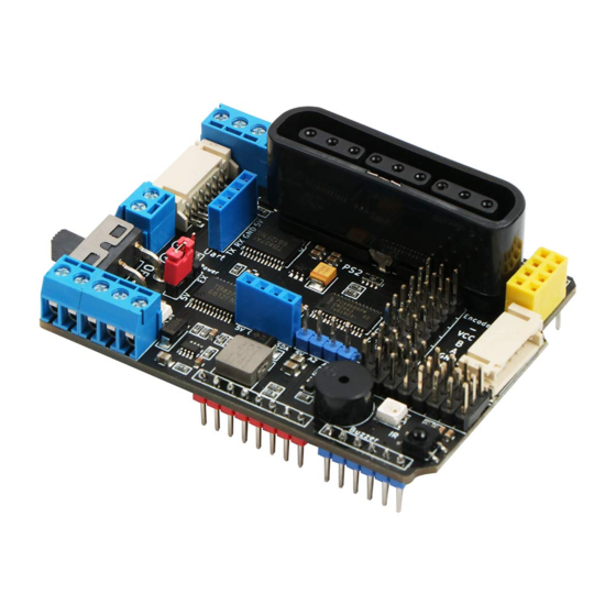
Overview The PS2X&Motor Driver Board driver can drive 4 DC motors, 2 encoder motors, 2 stepper motors, 6 servos (two external power supplies), and drive current up to 2A. The driver board is specially designed for the Arduino uno R3 motherboard. It can be directly plugged into the Arduino Uno.The motherboard integrates a passive buzzer, 2 RGB LED lights, and 1 infrared receiver. -
Page 6: Courseware Structure Diagram
NRF24L01 socket power supply RGB LED*2 DC motor port*4 Servo socket Passive buzzer*1 PS2X& Motor Driver Board Bluetooth / wifi interface switch PS2 port Ultrasonic socket Stepper motor port*2 Decoding motor port*2 Copy right © 2018 Shenzhen Emakefun Technology co., Ltd. -
Page 7: Driver Board Introduction
IN and 5V. Q:How many motors does the PS2X&Motor Driver Board can drive? A:The PS2X&Motor Driver Board can drive 4 DC motors ,2 stepper motors or 2 encoder motors. Q:How does PS2X&Motor Driver Board connect power drive servo?... -
Page 8: Software Installation
“arduino.exe” is very simple, it will not be explained here. It is recommended to quit the anti-virus software during the installation process, otherwise it may affect the IDE installation. After the installation is complete, click "arduino.exe" again to enter the IDE programming interface. Copy right © 2018 Shenzhen Emakefun Technology co., Ltd. -
Page 9: Install Driver
1)Firstly, right click on "My Computer" and open the Device Manager to view the ports (COM and LPT). At this point you will see a "USB Serial Port", right click on "USB Serial Port" and select the "Update Copy right © 2018 Shenzhen Emakefun Technology co., Ltd. - Page 10 Driver Software" option. Figure 4-3 Update Driver Copy right © 2018 Shenzhen Emakefun Technology co., Ltd.
- Page 11 2)Nextly, next select the "Browse my computer for driver software" option. Figure 4-4 Driver update selection interface 3)Finally select the driver file named "FTDI USB Drivers" located in the "Drivers" folder of the Arduino software download. Copy right © 2018 Shenzhen Emakefun Technology co., Ltd.
- Page 12 Figure 4-5 Select drive path Figure 4-6 install driver Copy right © 2018 Shenzhen Emakefun Technology co., Ltd.
- Page 13 At this time, we return to the "Device Manager" interface, the computer has successfully identified the Arduino, as shown in Figure 4-8, then open the Arduino compiler environment, you can open the Arduino journey. Figure 4-8 Drive successful identification interface Copy right © 2018 Shenzhen Emakefun Technology co., Ltd.
-
Page 14: Ide Interface Introduction
1、The first thing that catches your eye is the interface below. The toolbar button functions are "Compile" - "Upload" - "New Program" - "Open Program" - "Save Program" - "Serial Monitor", as shown in Figure 4-10. Copy right © 2018 Shenzhen Emakefun Technology co., Ltd. - Page 15 Port. In the Board option, we can see the commonly used Arduino development board models, you only need to choose according to the development board in your hand. In the Port option, the Copy right © 2018 Shenzhen Emakefun Technology co., Ltd.
- Page 16 USB serial port is mainly selected, as shown in Figure 4-13. If you are not sure, you can view it in the Device Manager and select the corresponding COM port. Figure 4-12 Tools interface Figure 4-13 USB Serial port selection Copy right © 2018 Shenzhen Emakefun Technology co., Ltd.
-
Page 17: Connect To The Arduino Uno R3 Development Board
Connect to the Arduino UNO R3 development board The pin header on the PS2X&Motor Driver Board can be plugged directly into the Arduino UNO R3 development board. No other flying lines are required. The pins are fully compatible and easy to install. -
Page 18: Dc Motor
Figure 5-1 Power schematic DC Motor Motor control principle The PS2X&Motor Driver Board uses the PCA9685 to output the PWM control motor driver chip TB6612FNG. Now we’ll briefly introduce the two chips. The main parameters of PCA9685 are as follows: ◆... - Page 19 For detailed use of the chip, please refer to《MotorDriverBoard\Datasheet\PCA9685.pdf》 TB6612FNG Introduction The PS2X&Motor Driver Board uses TB6612FNG to drive the motor. The TB6612FNG has a high-current MOSFET-H bridge structure, dual-channel circuit output, and a continuous drive current of up to 1.2 A per channel.
- Page 20 For detailed use of the chip, please refer to《MotorDriverBoard\Datasheet\TB6612FNG.pdf》 Driving DC motor The PS2X&Motor Driver Board has four DC motor interfaces, namely DC motor interface 1, DC motor interface 2, DC motor interface 3 and DC motor interface 4, which can be directly connected to the drive via the terminals.
- Page 21 Figure 6-3 DC Motor connection diagram Figure 6-4 Motor drive schematic Experimental procedure Open the IDE, load the file -> AdvancedExperiment->TB6612_DC_Motor-> TB6612_DC_Motor.ino Copy right © 2018 Shenzhen Emakefun Technology co., Ltd.
-
Page 22: Stepper Motor
5~12V. If the working voltage of the stepper motor is too low or too high, there is a phenomenon that the burned motor or the drive board collapses, and the battery should be Copy right © 2018 Shenzhen Emakefun Technology co., Ltd. -
Page 23: Encode Motor
A Hall encoder is a sensor that converts the amount of mechanical geometric displacement on an output shaft into a pulse or digital quantity by magnetoelectric conversion. The Hall encoder consists of a Hall code Copy right © 2018 Shenzhen Emakefun Technology co., Ltd. - Page 24 AB phase when the motor rotates. The encoder comes with a pull-up resistor, so no external pull-up is required and can be directly connected to the Copy right © 2018 Shenzhen Emakefun Technology co., Ltd.
- Page 25 The power of the board will find that the two encoder motors will rotate synchronously. The schematic diagram of the encoder motor is shown in Figure 6-4. Copy right © 2018 Shenzhen Emakefun Technology co., Ltd.
-
Page 26: Rgb Led Light
⚫ Built-in voltage regulator tube, only 24V power supply terminal only needs string resistor to IC VDD pin, no need to add regulator tube ⚫ Grayscale adjustment circuit (256 levels of grayscale adjustable) Copy right © 2018 Shenzhen Emakefun Technology co., Ltd. -
Page 27: Working Principle Of Ws2812 Rgb Led Light
Figure 9-1 and Table 1. Symbol Pin name Function description Logic power IC Power Supply supply LED Drive output Display data cascade output LED Drive input Display data input Ground Ground, finally cascaded Copy right © 2018 Shenzhen Emakefun Technology co., Ltd. -
Page 28: Ws2812 Rgb Led Light Driving Principle
24bit data structure Drive RGB LED light There are two RGB LED lights RGB1 and RGB2 on the PS2X&Motor Driver Board. You can control the RGB light-off timing by programming. You can also set the color of the RGB light (example program file Copy right ©... -
Page 29: Buzzer
There is no oscillation circuit inside the passive buzzer, and the working signal is a pulse signal of a certain frequency. If the passive buzzer for the DC signal is not responsive, the molybdenum sheet cannot vibrate because the magnetic path is constant. Copy right © 2018 Shenzhen Emakefun Technology co., Ltd. -
Page 30: Working Principle Of Buzzer
S8050 is used as an amplifying circuit. Drive buzzer There is a passive buzzer on the PS2X&Motor Driver Board. You can control the buzzer to play the prompt or play music by writing a program (example program file path: load file -> ArduinoDemo ->... -
Page 31: Drive Servo
DC motor and control circuit. Figure 11-1 and Figure 11-2 show the internal structure of the Servo. The Motor Driver Board uses a 180 degree SG90 (180 degree) 9g servo. Figure11-1 Diagram of Servo Copy right © 2018 Shenzhen Emakefun Technology co., Ltd. -
Page 32: Working Principle Of Servo
The direction and speed of rotation to achieve the target stop. The workflow is: control signal → control circuit board → motor rotation → gear set deceleration → steering wheel rotation → position feedback potentiometer → control circuit board feedback. Copy right © 2018 Shenzhen Emakefun Technology co., Ltd. -
Page 33: Drive Servo
Figure 11-3 Relationship between servo output angle and input pulse Drive Servo The PS2X&Motor Driver Board driver board can drive the servo, the servo pin position on the driver board (red pin), with ground pin (GND), power pin (VCC) and signal pin (S), three the pins are respectively connected to the corresponding pins of the servo (Fig. - Page 34 Note: The sample program file path is controlled by the I/O digital pin. If you need to control the servo through I2C, you need to connect the wiring of the servo to the corresponding interface in the schematic. Figure 11-4 MG90 Servo machine physical map Copy right © 2018 Shenzhen Emakefun Technology co., Ltd.
-
Page 35: How To Use An External Power Supply To Drive The Servo
The specific steps are as follows: 1) Short the power supply pin 5V and EX pin on the PS2X&Motor Driver Board through the jumper cap; 2) Connect the external power supply to the power connector on the PS2X&Motor Driver Board;... -
Page 36: Drive Ultrasonic Module
S = V· △t /2 Drive Ultrasonic Module The PS2X&Motor Driver Board has a four-wire ultrasonic module interface on the driver board. The four pins are the power supply pin (vcc), the ultrasonic signal transmission pin (A1), the ultrasonic signal receiving pin (A1), and the ground (GND). -
Page 37: Infrared Remote Control
When it is used, it only needs to be inserted into the Arduino. When there is an infrared coded signal transmission, after being processed by the infrared connector, the output is a square wave signal after the Copy right © 2018 Shenzhen Emakefun Technology co., Ltd. -
Page 38: Working Principle
Figure 13-2 Block diagram of the infrared transmitting and receiving system Driving infrared remote control There is an infrared remote control receiving probe on the PS2X&Motor Driver Board (as shown in Figure 14-1). (Example program file path: Load file -> ArduinoDemo -> IrkeyPressed -> IrkeyPressed.ino) After burning the sample program, turn on the power. - Page 39 It is more intuitive to see the effect of the infrared remote control. The schematic diagram of the infrared remote control is shown in Figure 14-3 Figure 14-1 Infrared receiver head physical map Copy right © 2018 Shenzhen Emakefun Technology co., Ltd.
-
Page 40: Ps2 Remote Control
The outstanding characteristic is that this kind of handle price is extremely high now. Key- rich, easy to extend to other applications, such as the picture 15-1 is a commonly used PS2 wireless handle. Copy right © 2018 Shenzhen Emakefun Technology co., Ltd. - Page 41 The handle is open, the receiver is powered, the handle and receiver will automatically pair, when the lamp is always bright, the handle pair succeeds. The key "mode" (handle batch is different, Copy right © 2018 Shenzhen Emakefun Technology co., Ltd.
-
Page 42: Drive Ps2 Remote
60 microseconds. The ACK port is not used in programming. Drive PS2 remote There is a PS2 port on the PS2X&Motor Driver Board. The PS2 infrared receiver can be directly plugged into the PS2 port. After the PS2 receiver is properly inserted (as shown in Figure 11-1), the sample program starts to be burned. - Page 43 PS2 remote control. The schematic diagram of the PS2 remote control is shown in Figure 15-3.。 Figure 15-2 PS2 Control Figure 15-3 Schematic diagram of the PS2 receiver Copy right © 2018 Shenzhen Emakefun Technology co., Ltd.
-
Page 44: Nrf2401
Drive NRF24L01+ module Insert the nRF24L01+ module into the corresponding interface on the PS2X&Motor Driver Board driver board (as shown in Figure 16-2). For the stable reception of Nrf24L01 data, it is recommended to connect 10uf capacitor between VCC and GUD as shown in Figure 16-3. - Page 45 Figure 16-2 Connection diagram of Nrf24l01+ Figure 16-3 Schematic diagram of the Nrf24l01+ connection Copy right © 2018 Shenzhen Emakefun Technology co., Ltd.
-
Page 46: Appendix
Appendix External sensor connection method In addition to the ultrasonic module socket and the servo jack, the PS2X&Motor Driver Board also reserves 10 sets of expansion pin interfaces, of which 6 are general digital I/0 interfaces and 4 are I2C control interfaces.
Need help?
Do you have a question about the PS2X and is the answer not in the manual?
Questions and answers