Advertisement
Available languages
Available languages
Quick Links
PACKAGE CONTENTS:
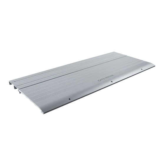
A2
A3
PART
A2
Threshold Plank (A2)
A3
Threshold Plank (A3)
NN
Screw, #8-18 x 1-1/2"
PFH #2 Tek
ATTACH YOUR RECEIPT HERE
Questions, problems, missing parts? Before returning to your retailer, call our customer
service department at 1-888-442-2923, 8 a.m. - 5 p.m., CST, Monday - Friday.
NN
Not to size
DESCRIPTION
QUANTITY
1
1
4
1
ITEM #254126, 254140
THRESHOLD
MODELS #RT536, RT548
Français p. 4 / Español p. 7
Lowes.com
Advertisement

Subscribe to Our Youtube Channel
Related Manuals for Gate House RT536


Summary of Contents for Gate House RT536
- Page 1 ITEM #254126, 254140 THRESHOLD MODELS #RT536, RT548 Français p. 4 / Español p. 7 PACKAGE CONTENTS: Not to size PART DESCRIPTION QUANTITY Threshold Plank (A2) Threshold Plank (A3) Screw, #8-18 x 1-1/2” PFH #2 Tek ATTACH YOUR RECEIPT HERE Questions, problems, missing parts? Before returning to your retailer, call our customer service department at 1-888-442-2923, 8 a.m.
- Page 2 ASSEMBLY INSTRUCTIONS 1. Slide together threshold planks (A2) and (A3). 2a. Position groove in threshold plank (A3) onto lip of side rail cover (B2). Fasten to threshold support wedge (B5) with #8-18 x 1-1/2” PFH #2 Tek screws (NN). Anchor to surface with 1/4 anchors suitable for your application. Hardware Used Hardware Recommended #8-18 x 1-1/2”...
- Page 3 2b. Set end threshold onto end of R100, R242, R342 or R442 kits. Fasten threshold plank (A2) to side rails (G) with 1-1/2” screws (NN). Adjust the location of plank (A2) to allow plank (A3) to hit ending surface. Anchor to surface with 1/4 anchors suitable for your application. Hardware Used Screw, #8-18 x 1-1/2”...
- Page 4 ARTICLES #254126 et 254140 SEUIL MODÈLES #RT536 et RT548 CONTENU DE L’EMBALLAGE : Grandeur non réelle PIÈCE DESCRIPTION QUANTITÉ Planche de seuil (A2) Planche de seuil (A3) Vis autotaraudeuse cruciforme 8-18 x 1 1/2 po à tête plate à pointe n JOIGNEZ VOTRE REÇU ICI...
-
Page 5: Instructions Pour L'assemblage
INSTRUCTIONS POUR L’ASSEMBLAGE 1. Faites glisser l’une dans l’autre les planches de seuil (A2) et (A3). 2a. Placez la rainure dans la planche de seuil (A3) sur la saillie du couvre-traverse latéral (B2). Fixez l’ensemble à la cale du support du seuil (B5) à l’aide des vis autotaraudeuse cruciforme n 8-18 x 1 1/2 po à... - Page 6 2b. Placez l’extrémité du seuil sur l’extrémité de l’ensemble R100, R242, R342 ou R442. Fixez la planche de seuil (A2) aux traverses latérales (G) à l’aide de vis de 1 1/2 po (NN). Réglez l’emplacement de la planche (A2) pour permettre à la planche (A3) d’atteindre la surface d’appui.
-
Page 7: Contenido Del Paquete
ARTÍCULO # 254126, 254140 UMBRAL MODELOS # RT536, RT548 CONTENIDO DEL PAQUETE: No se muestra en tamaño real PIEZA DESCRIPCIÓN CANTIDAD Plancha para umbral (A2) Plancha para umbral (A3) Tornillo autoperforante # 8-18 x 1-1/2 pulg PFH # 2 ADJUNTE SU RECIBO AQUÍ... -
Page 8: Instrucciones De Ensamblaje
INSTRUCCIONES DE ENSAMBLAJE 1. Deslice y una las planchas para umbral (A2) y (A3). 2a. Coloque la ranura de la plancha para umbral (A3) en la lengüeta de la cubierta del riel lateral (B2). Sujete a la cuña de soporte de umbral (B5) con tornillos autoperforantes # 8-18 x 1-1/2 pulg PFH # 2 (NN). - Page 9 2b. Coloque el extremo del umbral en el extremo del kit R100, R242, R342 o R442. Sujete la plancha del umbral (A2) en los rieles laterales (G) con los tornillos de 1-1/2 pulg (NN). Ajuste la ubicación de la plancha (A2) para permitir que la plancha (A3) se adhiera a la superficie del extremo.
Need help?
Do you have a question about the RT536 and is the answer not in the manual?
Questions and answers