Table of Contents
Advertisement
Quick Links
Advertisement
Table of Contents

Related Manuals for Renogy RMS-LFPS-US

Summary of Contents for Renogy RMS-LFPS-US
- Page 1 MONITORING SCREEN FOR SMART LITHIUM BATTERY SERIES Version 1.2...
- Page 2 Important Safety Instructions Please save these instructions. This manual contains important installation and operation instructions for the Renogy monitoring screen. Please review and observe these instructions and keep them located near the monitoring screen for further reference. The following symbols are used throughout the manual to indicate potentially dangerous conditions or important safety information.
- Page 3 DO NOT puncture, drop, crush, burn, penetrate, shake, or strike the monitoring screen. DO NOT open, dismantle, or modify the monitoring screen. The monitoring screen is only compatible with Renogy Smart Lithium Iron Phosphate Batteries. DO NOT attempt to connect the monitoring screen to other batteries or systems.
-
Page 4: Table Of Contents
Table of Contents General Information Key Features Product Overview Identification of Parts Dimensions Additional Components Installation Preparation Choosing an Installation Location Mounting the Monitoring Screen Connecting to the Battery Operation LCD Information Button Operation Troubleshooting Technical Specifications... -
Page 5: General Information
General Information The Renogy Monitoring Screen for Smart Lithium Battery Series is a high precision meter designed for Smart Lithium Iron Phosphate Batteries in off-grid energy storage systems. Instead of measuring the current flowing in/out of the battery bank, it... -
Page 6: Product Overview
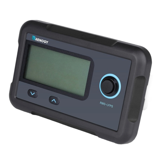
Product Overview Identification of Parts ① ② ③ ④ ⑤ ⑧ ⑥ ⑦ ① ⑤ LCD Screen Front Cover Plate ② ⑥ Page Down Button RJ45 Communication Port ③ ⑦ Page Up Button Mounting Hole ④ ⑧ Power Button Snap-Fit Joint Dimensions 4.3in 1.3in... -
Page 7: Additional Components
3.4in 87.5mm Additional Components RJ45 Communication Cable The RJ45 Communication Cable (5m / 16.4 ft) is used to connect the monitoring screen to the battery bank for power supply and data transmission. Self-Tapping Screws (4) The Self-tapping Screws (M2.9 x 13) are used fix the monitoring screen on the mounting surface. -
Page 8: Choosing An Installation Location
Choosing an Installation Location Please choose a clean, dry, protected, and easily accessible indoor location to install the monitoring screen. It is recommend- ed to mount the monitoring screen at eye level for easy access of operational controls and battery information. The RJ45 Communication Port is accessible from the back of the monitoring screen. -
Page 12: Connecting To The Battery
Connecting to the Battery Please connect the monitoring screen to the RS485 UP Communication Port of the battery using the included RJ45 Communication Cable to obtain detailed battery information from the battery management system. RJ45 Communication Port RJ45 Communication Cable RS485 UP Communication Port... - Page 13 If the monitoring screen is used with a parallel battery bank, the communication between paralleled batteries must be enabled. Please connect the RS485 LINK Communication Ports of the former batteries to the RS485 UP Communication Ports of the latter ones using CAT5 (or above) Ethernet straight through cables (not included).
-
Page 14: Operation
Please avoid too high a voltage difference between paralleled batteries, despite the auto-balancing function, to avoid triggering the over-current protection. In parallel battery banks, the copper cables between each battery should be of equal length to ensure that all batteries in the system can work equally together. - Page 15 The present voltage indicates the real-time terminal voltage of the battery. If the monitoring screen is used with a battery bank, the present voltage will be the average terminal voltage of the batteries in the battery bank. Present Current (A) The present current indicates the real-time current flowing through the battery or the battery bank.
- Page 16 Self-Heating Function Status The self-heating function status indicates the operation status of the self-heating function. If the self-heating function is not available or not operating, the self-heating function status will be ‘0’. If the self-heating function is available and operating, the self-heating function status will be ‘H’.
- Page 17 Battery Level The battery level indicates the real-time charge level of the battery relative to its capacity using four battery segments. If the battery is being charged, the battery segments will illuminate one by one repeatedly until the battery is fully charged.
-
Page 18: Button Operation
Error Code Battery Operation Status Battery Over-Voltage Protection / Battery Cell Over-Voltage Protection Battery Under-Voltage Warning Charge Over-Current Warning Discharge Over-Current Warning Battery High Temperature Protection (Charge) Battery Low Temperature Protection (Charge) The communication between paralleled batteries MUST be enabled using CAT5 (or above) Ethernet straight through cables before connecting the battery bank to the monitoring screen to obtain the accurate battery bank information. -
Page 19: Troubleshooting
If any problems occur during the operation of the monitoring screen, please refer to the following instructions or contact Renogy for assistance: If the monitoring screen does not operate after connecting to the battery or the battery bank, please check monitoring screen side and battery side connections. - Page 20 If the battery information displayed on the monitoring screen is not accurate, please long press the Page Up Button and Page Down Button at the same time for 3 seconds to reset the monitoring screen and refresh the battery information. If the monitoring screen resets frequently or does not display battery information, please reactivate the battery or the battery bank using the Power Button on the monitoring...
-
Page 21: Technical Specifications
Technical Specifications Electrical Specifications Operating Voltage 12VDC Operating Current 30mA Power Consumption <1W Operating Temperature -4°F~113°F / -20°C~45°C Voltage Accuracy ±0.1V Current Accuracy ±0.1A Capacity Accuracy ±0.1Ah Certification FCC Part 15 Class B, CE, RoHS Mechanical Specifications Communication Port RJ45 (RS485 Protocol) Display Backlit LCD 2 Front Panel Menu Buttons,... - Page 22 FCC Compliance: This device complies with Part 15 of the FCC Rules. Operation is subject to the following two conditions: (1) this device may not cause harmful interference, and (2) this device must withstand any interference received, including interference that may cause undesired operation.
- Page 24 RENOGY.COM Renogy reserves the right to change the contents of this manual without notice. 2775 E Philadelphia St, Ontario, CA 91761, USA 909-287-7111 www.renogy.com support@renogy.com 400-6636-695 https://www.renogy.cn support@renogy.cn https://www.renogy.jp supportjp@renogy.com https://ca.renogy.com supportca@renogy.com https://au.renogy.com supportau@renogy.com https://uk.renogy.com supportuk@renogy.com https://de.renogy.com supportde@renogy.com...
Need help?
Do you have a question about the RMS-LFPS-US and is the answer not in the manual?
Questions and answers