Table of Contents
Advertisement
Quick Links
Installation & Maintenance Instructions
2-WAY INTERNAL PILOT-OPERATED SOLENOID VALVES NORMALLY CLOSED
OPERATION - ¾" , 1" , 1¼" , 1½" , 2", 2½" OR 3" NPT
NOTICE:
See
separate
Maintenance instructions for information on: Wiring,
Solenoid Temperature, Causes of Improper Operation, and
Coil Replacement.
For exploded views, see I&M No. V9564R5 - Section 2.
DESCRIPTION
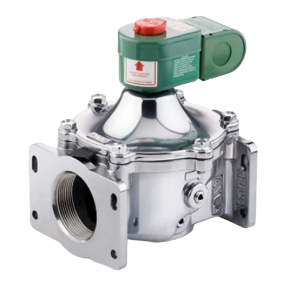
Series 8214(200) valves are 2-way normally closed diaphragm-
type solenoid valves designed for fuel gas service. Valve bodies
are made of rugged aluminum with trim and internal parts made
of steel and stainless steel. Series 8214 (200) valves maybe
provided with a general purpose, general purpose junction box
or watertight solenoid depending upon basic valve construction.
The valves feature mounting flanges on the inlet and outlet of the
valve. These flanges allow like valves to be mounted together
in series without the use of an intermediate pipe nipple. This
feature is intended for applications where two redundant valves
are required by a governing body. The mounting of the two
valves in series is accomplished with an optional connecting
hardware kit. Please see additional instructions for the use of
this kit in the Piping section of this I&M sheet.
Valve catalog numbers with Suffix C have an integral electrical
and visual position indicator and proof of closure construction.
Valves with Suffix VI (in the catalog number)have a visual only
position indicator. The position indicator gives visual indication
of Open and Shut positions by means of a small ball. The ball
travels up and down in a transparent holder between labels Open
and Shut. Electrical indication is accomplished by the operation
of a single pole single throw reed switch. Reed switch contact
is closed when solenoid is de-energized; open when energized.
Note: Position indicators not available for DC valves.
Provisions for Pressure and Seat Leakage Testing
(See Figure 1.)
Series 8214 (200) valves are provided with four 1/8" NPT
tapped and plugged holes, two on either side of valve body.
Two upstream for pressure testing; two downstream for seat
leakage testing. Leakage testing frequency shall be at least
annually in accordance with NFPA
manufacturer recommendations. Testing is also required after
Valve Disassembly and reassembly for inspection, cleaning or
rebuilding.
OPERATION
Normally Closed: Valve is closed when solenoid is de-energized;
open when energized.
Minimum 0 psig
INSTALLATION
Check nameplate for correct catalog number, pressure, voltage,
frequency, and service. Never apply incompatible fluids or
exceed pressure rating of the valve. Installation and valve
maintenance to be performed by qualified personnel.
ASCO Valves
®
ASCO Valve, Inc.
50 Hanover Road,Florham Park, New Jersey 07932 www.ascovalve.com
©
®
FUEL GAS SERVICE
solenoid
installation
and
86 or original equipment
-
Maximum 5 psig
E229013 - 08/12
I&M No. V 9564_Sec1 R5
Temperature Limitations
For valve ambient and fluid temperatures, refer to chart
Catalog
Service AC
Numbers i
or DC i
8214235
AC or DC
8214240
AC
8214250
AC or DC
8214260
AC or DC
8214265
AC or DC
8214270
AC or DC
8214275
AC or DC
8214280
AC or DC
8214285
AC
8214290
AC
Note:
Includes catalog numbers with or without Suffix C or VI.
i
Positioning
Catalog Numbers 8214235, 250, 260, 265, 270, 280 with AC
voltage and without Suffix C or VI can be mounted with
solenoid in any position horizontal and above.
Catalog numbers 8214240, 285, 290 must be mounted with
solenoid in the vertical-upright position.
All Catalog Numbers with DC voltage must be mounted with
solenoid in the vertical-upright position.
All Catalog Numbers with Suffix C or VI must be mounted with
solenoid in the vertical-upright position.
Connect piping to valve according to markings on valve body.
Apply pipe compound sparingly to male pipe threads only. If
applied to valve threads, the compound may enter the valve
and cause operational difficulty. Avoid pipe strain by properly
supporting and aligning piping. When tightening the pipe, do
not use valve or solenoid as a lever. Locate wrenches applied
to valve piping as close as possible to connection point. Locate
wrenches applied to valve body per Figure 1. Valve should
be checked for external leakage at piping connections after
installation, see Testing for External Leakage section.
These valves feature mounting flanges on the inlet and outlet of
the valve for direct connection to one another or connection in
a valve train with an optional Flange Adapter Kit. The optional
Flange Adapter Kit may also be used in place of direct piping
for easy maintenance and disassembly of the valve without
breaking any NPT pipe connections. This feature may only be
used with an optional ASCO connecting hardware kit containing
approved hardware and seals. The use of hardware and seals that
are not part of the kit will void your warranty. Please refer to
Installation & Maintenance Instructions, I&M No. V9567 for kit
part numbers and contact ASCO for availability.
All Rights Reserved.
SERIES
8214(200)
Insulation
Min. & Max. Ambient
Class
& Fluid Temp
F, H, B
ClassF (AC)
F
-40 °F (-40 °C) to
125 °F (52 °C)
F, H, B
F, H, B
Class H (AC)
F, H, B
-40 °F (-40 °C) to
F, H, B
140 °F (60 °C)
F, H, B
F, H, B
Class B (DC)
-40 °F (-40 °C) to
F
77 °F (25 °C)
F
I&M No.V9564R5
Page 1 of 8 (Section 1 of 2)
Advertisement
Table of Contents

Subscribe to Our Youtube Channel
Related Manuals for ASCO Valves 8214(200) Series


Summary of Contents for ASCO Valves 8214(200) Series
- Page 1 ASCO for availability. frequency, and service. Never apply incompatible fluids or exceed pressure rating of the valve. Installation and valve maintenance to be performed by qualified personnel. I&M No.V9564R5 ASCO Valves ® E229013 - 08/12 All Rights Reserved. ASCO Valve, Inc.
- Page 2 Cleaning WARNING: To prevent the possibility of death, All solenoid valves should be cleaned periodically. The time serious injury or property damage, only use the between cleanings will vary depending on the medium and optional ASCO connecting hardware kit for the direct service conditions.
- Page 3 3. Open the upstream manual gas cock. Program the control Valve Reassembly system to energize and maintain the valve in the open 1. Lubricate bonnet gasket and body gasket with a light coat (energized) position. Check all valve and piping of DOW CORNINGr 200 Fluid lubricant or an connections for external leaks with rich soap and water equivalent high---grade silicone fluid.
- Page 4 When ordering Rebuild Kits careful attention to exploded view provided in Figure 3 for ASCO valves, order the Rebuild Kit number stamped on for identification and placement of parts. the valve nameplate. If the number of the kit is not visible, 4.
- Page 5 Figure 1. Figure 2. Series 8214(200) valve without solenoid Figure 3. Visual position indicator (partial view) AC Construction I&M No.V9564R5 ASCO Valves ® E229013 - 08/12 All Rights Reserved. Page 5 of 8 (Section 2 of 2) ASCO Valve, Inc.
- Page 6 Suffix C solenoid base sub---assembly bonnet screw (6) bonnet gasket IMPORTANT valve bonnet See Torque and Lubrication Chart core/diaphragm sub---assembly Locate bleed hole in core/diaphragm sub--- bleed hole assembly approximately 30° from valve inlet CAUTION body gasket Do not damage valve seat Rebuild Kits are not available for valves...
- Page 7 DC Construction Open end wrench available for solenoid base solenoid base sub---assembly sub---assembly (order no. K168146---1) Pin holes for special wrench adapter supplied in ASCO Rebuild Kit. For wrench adapter only order no.K218949 (standard wrench) housing wrenching flat 1/2I NPT conduit connection bonnet screw (6) bonnet gasket...
- Page 8 To illustrate leakage testing only. Not for system layout. Series 8214(200) Combustion Valves upstream downstream manual manual gas cock gas cock leak test tap gas supply to burner downstream pressure tap external leak test tap option test petcock 1/4I flex tubing 1/4I aluminum or copper pilot tubing glass jar...
Need help?
Do you have a question about the 8214(200) Series and is the answer not in the manual?
Questions and answers