Advertisement
Quick Links
Advertisement

Related Manuals for York YCAZ88EE8


Summary of Contents for York YCAZ88EE8
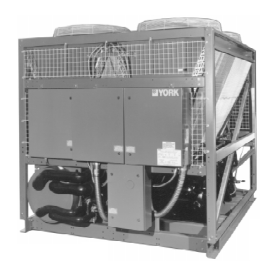
- Page 1 RecipPak LIQUID CHILLERS AIR COOLED - RECIPROCATING HERMETIC 26174A fi 200, 230, 460-3-60...
- Page 4 26174A LD02159 25212A 26175A 2521 1A...
- Page 5 26068A 26069A...
- Page 6 27299 27298A 27297A...
- Page 7 LD02160 CAUTION: Excessive flow will cause damage to the cooler. Do not exceed maximum cooler GPM. Special care should be taken when multiple chillers are fed by a single pump.
- Page 8 LD02161...
- Page 10 DUAL COMPRESSOR POWER SUPPLY WIRING (STANDARD) SYSTEM #1 WIRING SYSTEM #2 WIRING MODEL MAX. MAX SIZE INCOMING COND MAX. MAX SIZE INCOMING COND DUAL ELEM DIS. CKT. BKR. WIRE RANGE CPR CPR FAN MCA DUAL ELEM DIS. CKT. BKR. WIRE RANGE CPR CPR FUSE MIN.
- Page 11 SINGLE POINT POWER SUPPLY WIRING (OPTIONAL) MAX SIZE DUAL ELEM INCOMING DIS. CKT. BKR. YORK SUPPLIED DISCONNECT FUSE SIZE WIRE RANGE MIN. HACR (CU ONLY) (CU ONLY) MIN. MAX. TYPE LEGEND: (1 -3) #6-350MCM (1-2) #4/0-500MCM VOLT = Voltage (1-3) #6-350MCM...
- Page 12 26174A(R)
- Page 13 Ground Level Locations...
- Page 14 LD02163 Type & Size Max. Load, Ibs. (Kg) Spring Color Defl., ins. (mm) Type & Size Max. Load, Ibs. (Kg) Spring Color Defl., ins. (mm) CP-2-25 (408.2) 1.22 (30.9) CP-4-25 1800 (816.4) 1.22 (30.9) CP-2-26 1200 (544.3) Purple 1.17 (29.7) CP-4-26 2400 (1088.6) Purple...
- Page 15 WARNING: Flow switch must not be used to stop and s t a r t c h i l l e r . I t i s i n t e n d e d o n l y a s a s a f e t y s w i t c h .
- Page 16 LD02165...
- Page 17 LD02166...
- Page 18 LD02167 LD02168 LD02169...
- Page 19 LD02170...
- Page 20 LD02171...
- Page 21 LD02172...
-
Page 22: Microprocessor Board
26572A(D) MICROPROCESSOR BOARD... - Page 23 CURRENT TRANSFORMER (C.T.) φ 40 CHARACTER DISPLAY KEYPAD RELAY OUTPUT BOARD BATTERY BACK-UP 26176A...
- Page 24 25999A 26000A...
- Page 25 26572A(D)
- Page 27 LD01943 26001A LD01944...
- Page 30 26572A(D)
- Page 33 26572A...
- Page 34 26572A THESE VALUES MAY CAUSE DAMAGE TO THE CHILLER OR OPERATION PROBLEMS. NOTE: In some water cooled condenser installations, the possibility exists for the condenser water pump or the cooling tower to not be in operation when the chiller starts. This causes the dis- charge pressure to rise so rapidly that even though the mechanical high pressure cut-out is shutting down the compressor, t h e f l y w h e e l e f -...
- Page 35 NOTE: It is required to first key in a “0” when program- ming this cut-out (Example: 0395 PSIG). NOTE: Operation below 0°F may cause other types of nuisance safety shutdowns, but occasional shut- downs can usually be tolerated since the need for sustained operation at these temperatures is unlikely and temperatures rarely stabilize for any length of time below 0°F.
- Page 36 NOTE: It is required to first key in a “0” when program- ming this cut-out (Example: 0375 PSIG). NOTE: When programming values from 80-99 PSIG, it is required to first key in a “0”. Example: 085 PSIG.
- Page 37 NOTE: There are some exceptions where suction pres- sure is permitted to temporarily drop below the cut-out point. Details are outlined in the SYS- TEM SAFETIES section. NOTE: Hot Gas Bypass (Loadminder) should not be counted for programming purposes.
- Page 38 26572A...
- Page 39 NOTE: This will have no effect on the holiday schedule. NOTE: Only one start/stop time can be programmed which will apply to each of the “HOLIDAY” days selected.
- Page 40 “THE FOLLOWING ARE PROGRAMMED” “RETURN WATER CONTROL” or “LEAVING WATER CONTROL”...
- Page 41 NOTE: In LWT CONTROL, water temperature may un- desirably rise when a compressor cycles off and cannot restart because the anti-recycle timer is still timing out. The effects can be reduced by programming the anti-recycle timer (Page 36) for a minimum of 300 seconds if it isn’t already pro- grammed for 300 seconds.
- Page 42 ∆ ∆ ∆ “RETURN WATER TEMP CONTROL” is...
- Page 43 NOTE: When programming values between 0.1° - 9.9 °F, i t i s r e q u i r e d t o f i r s t k e y i n a “ 0 ” o r “ 0 0 ” . E x - ample: 05.9°F.
- Page 44 NOTE: Too small of a RATE SENSITIVlTY value se- lection may prevent loading due to varying flows or if the water system allows a slug of cold water to enter which falsely fools the micro into think- ing the RATE SENSlTIVlTY has been ex- ceeded, preventing loading and allowing leaving water temperature to rise above the desired temperature.
- Page 45 CAUTION: Too small of a CR selection will cause com- pressor/loader cycling. If compressor cycling occurs, leaving water temperature may vary considerably as a result of a compressor that cannot restart due to the anti-recycle timer. To eliminate this, increase the ∆ T (temperature differential) of the CR and/or program the anti-recycle timer for a mini- mum of 300 seconds if it isn’t already pro-...
- Page 46 NOTE: When programming values between 0.1° - 9 . 9 ° F , i t i s r e q u i r e d t o f i r s t k e y i n a “ 0 ” o r “ 0 0 ” . Example: 0.5°...
- Page 47 NOTE: Too small of a RATE SENSITIVITY Selection may prevent loading due to varying flows or if the water system allows a slug of cold water to enter which falsely fools the micro into thinking the RATE SENSITIVITY has been exceeded, pre- venting loading and allowing leaving water tem- perature to rise above the desired temperature.
- Page 48 LD02174 LD02175 NOTE: 7 Step Loading/Unloading is Not Presently Available.
- Page 49 NOTE: The micro controls loading and unloading re- sponses on a 10 step scale regardless of the number of stages present. Therefore, loading and unloading responses on 5 & 7 step chillers may appear delayed (time between steps in- creased) when missing steps are activated or de-activated by the micro, 5 STEP CONTROL IS STANDARD.
- Page 50 LD02176 NOTE: 7 Steps Loading / Unloading is not presently available.
- Page 51 NOTE: Do not confuse FLA and RLA. FLA (full load amps) is approximately 1.2 x RLA. RLA (running load amps) specified on the motor nameplate, is typical current demand under rated operating conditions in a fully loaded system. Therefore, do not expect to see 100% FLA when the sys- tem is fully loaded.
- Page 52 NOTE: LLSV refers to liquid line solenoid valve. NOTE: This safety is only operable if optional discharge pressure transducers are installed.
- Page 53 CAUTION: NEVER BYPASS A FLOW SWITCH. THIS WILL CAUSE DAMAGE TO THE CHILLER AND VOID ANY WARRANTIES.
- Page 55 26572A(D) LD02127...
- Page 56 LD02177 NOTE: In actual printouts, this would be one continuous printout.
- Page 61 NOTE: The micro will attempt to control the Hot Gas, Solenoid Valve regardless of whether the option i s i n s t a l l e d . NOTE: The micro will attempt to control the Hot Gas Solenoid Valve regardless of whether the option i s i n s t a l l e d .
- Page 62 , YORK will not be liable for damages.
- Page 63 26000A 26001A LD02178...
- Page 64 LD02179 26001A NOTE: ALL PROGRAMMED VALUES AND-STORED DATA, OTHER THAN THE INTERNAL CLOCK TIME-KEEPING, WILL BE MAINTAINED IN MEMORY REGARDLESS OF WHETHER THE CLOCK IS ON OR OFF AND REGARDLESS OF THE LENGTH OF THE POWER FAILURE.
- Page 65 NOTE: If a power failure should again occur, the above process will again need to be repeated to bring t h e c h i l l e r b a c k o n l i n e .
- Page 66 NOTE: Remote Setpoint Reset will not operate when a Remote Control Center Option Kit is connected to the Micro Panel. The Remote Control Center will always determine the setpoint. CAUTION: Two cautions should be observed when us- ing these functions. Observing these cau- tions will assure that undesirable operation does not result.
- Page 67 LD02180 NOTE: Optional Steps of Unloading are Not Available.
- Page 68 LD02182 LD02181 NOTE: 6 cylinder compressors do not connect the loading sole- NOTE: 6 cylinder compressors do not connect the loading sole- noid wiring on cylinders 1 & 2, effectively making them noid wiring on cylinders 1 & 2, effectively making them permanently loaded in the “standard”...
- Page 69 CAUTION: Compressor lubrication circuit must be primed with YORK “C” oil prior to start-up. Priming should be done through the Schrader fitting at the compressor oil pump. Stroke oil pump 10 times to prime the lubri- c a t i o n c i r c u i t .
- Page 70 NOTE: It is IMPORTANT that all switches are properly programmed. Otherwise, undesirable operation w i l l r e s u l t .
- Page 71 will deviate from normal sequence and timing previously described. When a compressor starts, internal timers limit minimum time before another compressor can start to 1 minute. Time between stages of loading is also limited by in- ternal timers to a minimum of 1 minute, al- though the micro would like to load at 30 sec- onds intervals which may cause the lag com- pressor to start before the lead system fully...
- Page 73 NOTE: If suction or discharge valves are not seated properly, a 1000 micron vacuum can not be obtained. Do not evacuate for long periods of time.
- Page 74 NOTE: Any inductive devices (con/actor/relay coil) con- nected to these contacts must be suppressed with YORK P/N 031-00808 supplied by others. Otherwise, nuisance faults may occur. LD02183...
- Page 75 LD02178 NOTE: Any inductive devices (contactor/relay coil) con- nected to these contacts must be suppressed with YORK PAN 031-00808 supplied by others. Otherwise, nuisance faults may occur. NOTE: Occasional operation below 0°F is normally pos- sible. In these cases a low suction pressure shutdown may sometimes occur, but can usu- a l l y b e t o l e r a t e d .
- Page 76 NOTE: The corresponding compressor must be on for 4 seconds before these fans are permit- t e d t o s t a r t . NOTE: The corresponding compressor must be on for 4 seconds before these fans are permit- t e d t o s t a r t .
- Page 77 NOTE: The microprocessor will only activate the hot gas on the lead compressor. NOTE: Fans with reversing contactors will have the reversing contactors mechanically locked out when the fans are running forward. The forward contactor will also be locked out when the fans are running in reverse.
- Page 78 NOTE: Hot gas should not be considered as an addi- tional step of unloading when programming the number of steps of loading/unloading. LD02184...
- Page 80 LD02185 NOTE: The print-out is made to be universal to all types of chillers both air and water cooled with or with- out options. Items may be indicated on the 23889A print-out which may not be present on the c h i l l e r .
- Page 81 LD02186...
- Page 83 00001TG LD02187...
- Page 84 LD02188...
- Page 85 25245A LD02189...
- Page 86 CAUTION: THE 4-20mA INPUT SIGNAL WIRING MUST NOT BE EARTH GROUNDED! NOTE: The coil of the controls used for reset must be suppressed. Use YORK P/N 031-00808-000 suppressor. The Remote Setpoint Reset will not operate when a Remote Control Center Option is con- nected to the micropanel.
- Page 87 Contact YORK Service Before Replacing Circuit Boards! Ω Contact YORK Service Before Replacing Circuit Boards or C.T.s!
- Page 88 NOTE: If external H.P. Cut-out Switch opens, a “Motor Current” Fault w i l l r e s u l t . NOTE: Operation NOTE: For occasional operation below below 25°F 0°F set the cut-out at 0°F. The requires low chiller is then allowed to operate ambient accessory.
- Page 89 ∆ ∆ NOTE: I t i s n o t u n u s u a l t o f i n d u p t o a 2°F difference between the display and a thermometer located in waterpiping.
- Page 92 Proud Sponsor of the 1998 U.S. Olympic Team 36USC380 P .O. Box 1592, YORK, Pennsylvania USA 17405-1592 Subject to change without notice. Printed in USA Copyright © by YORK International Corporation 1997 ALL RIGHTS RESERVED Form 150.60-NM3 (595) Supersedes: 150.60-NM2 in ERR only...