
Related Manuals for Holatron RAPID-FIRE 6

Summary of Contents for Holatron RAPID-FIRE 6
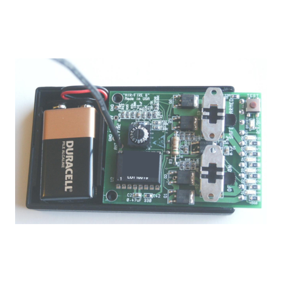
- Page 1 OPERATION & MAINTENANCE GUIDE - RAPID-FIRE 6 Compact Pairable Receiver (shown with cover removed) HOLATRON SYSTEMS, LLC 2800 Woodlawn Dr, Ste. 138 HONOLULU, HI 96822, USA (808) 732-5419 www.holatron.com...
- Page 2 Holatron Systems, LLC, from same, whether brought by the user, user’s agent, or assigns, or any third party.
-
Page 3: Hardware Description
“paired” with the desired cue range, channel #, and proprietary system code of any Holatron transmitter on a matching frequency via a very simple operation. The channel # (1-12) can optionally be selected via an internal digital switch, overriding the paired channel #. - Page 4 Rcvr Digital Switch Setting Action Pair with xmtd cue range (1-6 or 7-12), channel, & system code Fire paired cue range, channel 1, and paired system code. Fire paired cue range, channel 2, and paired system code. Fire paired cue range, channel 3, and paired system code. Fire paired cue range, channel 4, and paired system code.
- Page 5 FIGURE 1 (top view) Page 5 of 13...
- Page 6 FIGURE 2 (bottom view) Page 6 of 13...
- Page 7 The user has access to the following components (refer to figures 1 & 2): THE ANTENNA. The RF signal is received by a quarter-wave bendable antenna consisting of a permanently attached piece of 20 AWG solid insulated wire. If this wire should ever be damaged, it should be replaced with a similar wire of exactly 7 1/8”...
-
Page 8: The Test Button
THE OUTPUT CONNECTORS. Electric matches or other igniters are connected to this miniature terminal block with 10 screw terminals located on the bottom of the circuit board. A miniature screwdriver is required to secure the connections. Simply insert one wire from each of the 6 devices to be fired into its corresponding hole in the FIRE OUPUTS block. - Page 9 FIGURE 3 (bottom view) Page 9 of 13...
- Page 10 RADIO INTERFERENCE REDUCTION. For obvious safety reasons, Holatron's design goal is to ensure that data communication errors due to radio interference or to insufficient signal strength due to low battery, exceeding specified range, or conductive objects in the signal path will result in failure of intentional actuation rather than unintended actuation.
-
Page 11: Specifications
SPECIFICATIONS. Parameter Minimum Typical Maximum Carrier Frequency, MHz. 417.96 418.02 418.08 Carrier Frequency, MHz. (optional) 433.86 433.92 433.98 Range (line-of-sight with RFLS-1XT xmtr) ½ mile Delay from start of transmission to receiver output 75 msec 150 msec Receiver battery drain, (Rcvr switch on) 8 mA 9 mA Receiver battery drain, (Rcvr switch off) - Page 12 4.1.2 Connect devices to receiver outputs as described in section 1.4 above. The operator should retain possession of the transmitter or transmitter key while performing the next two tasks. With the “ARM” switch turned off, turn on the receiver power switch. Verify continuity through the devices by pressing the “TEST”...
-
Page 13: Maintenance
NOT water tight, however. The transmitter and receiver must never be immersed in water. If further information or service is required, contact: Holatron Systems, LLC. 2800 Woodlawn Dr, Suite 138, Honolulu, HI 96822, USA (808) 732-5419 charlie@holatron.com...
Need help?
Do you have a question about the RAPID-FIRE 6 and is the answer not in the manual?
Questions and answers