
Summary of Contents for LCI HF-320 a Series
- Page 1 Transport Drive Inverter Series Sensorless Vector Inverter TPSI TD-1 LOCHABER CORNWALL, INC.
- Page 2 7A5: 7.5kW S: 1-Phase 200V A75: 0.75kW 3A7: 3.7kW Easy Access to High Performance ! ■ High Torque ■ Built-in Noise Filter ■ Easy-Maintenance and Long Lifetime ■ Compact Corresponds to major standards of the world LCI FURNACES - TPSI...
- Page 3 Inverter 3-Phase 200V - 240V Specifications Specification Item Input Voltage Class 3-Phase 200V Motor HP (kW) 0.25 (0.2) 0.5 (0.4) 1 (0.75) 2 (1.5) 3 (2.2) 5 (3.7) 7.5 (5.5) 10 (7.5) 15 (11) 20 (15) Type HF3212- Motor Output Capacity (kVA) 1.6 (1.5) 3.3 (3.3) 5 (4.4)
-
Page 4: Explanation Of Function
G Communications circuit boards supporting DeviceNET, LonWorks, and so on are on the drawing board. LCI FURNACES - TPSI TD-4... - Page 5 Before Using Our Inverters ■ Selecting the Capacity (Model) of the Inverter Note 2. The maximum allowable torque at 50Hz can be calculated approximately by multiplying the maximum allowable torque at a Selection base frequency of 60Hz by 0.8. ● Capacity ●...
-
Page 6: Operation
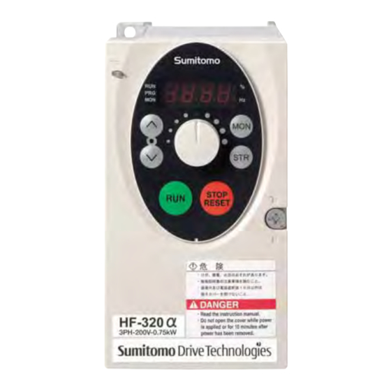
Pressing this key while the RUN Every pressing of this key while Lights when the RUN key is Down key key lamp is lighted starts the RUN key lamp is will cause enabled. operation. a slowdown stop. LCI FURNACES - TPSI TD-6... - Page 7 Set the frequency with the notches on the potentiometer. Move clockwise for the higher frequencies. The potentiometer has hysteresis. So the set value may slightly change when the inverter is turned off, and then turned back on. LCI FURNACES - TPSI TD-7...
- Page 8 LCI FURNACES - TPSI TD-8...
-
Page 9: Common Specification
Common Specification Item Specification Control system Sinusoidal PWM control Rated output voltage Adjustable within the range of 50 to 600V by correcting the supply voltage (not adjustable above the input voltage) Output frequency range 0.5 to 500.0Hz, default setting: 0.5 to 80Hz, maximum frequency: 30 to 500Hz Minimum setting steps of frequency 0.1Hz: operation panel setting, 0.2Hz: analog input (when the max. -
Page 10: Protective Functions
· The load is too large. Motor overload · The V/F setting is improper. · The motor is locked up. · Low·speed operation is performed continuously. · An excessive load is applied to the motor during operation. LCI FURNACES - TPSI TD-10... -
Page 11: Terminal Functions
Terminal Functions I Main Circuit Teminal Functions Terminals symbol Terminal function Grounding terminal for connecting inverter. There are 3 terminals in total. 2 terminals in the terminal board, 1 terminal in the cooling fin. 200V class: single-phase 200~240V-50/60Hz *Single-phase input: R/L1 and S/L2 terminals R/L1, S/L2, T/L3 3-phase 200~240V-50/60Hz 400V class: 3-phase 380~500V-50/60Hz... -
Page 12: Standard Connection Diagram
*2: The inverter came with the P1 and the P(+) terminals shorted by means of a shoeting bar. Before installing the DC reactor (DCL), remove the bar. *3: When using the DRV output terminal in sink logic mode, short-circuit the OM and COM terminals. LCI FURNACES - TPSI TD-12... - Page 13 *2: The inverter came with the P1 and the P(+) terminals shorted by means of a shoeting bar. Before installing the DC reactor (DCL), remove the bar. *3: When using the OM output terminal in source logic mode, short-circuit the P24V and DRV terminals. LCI FURNACES - TPSI TD-13...
- Page 14 Multi-stage speed 2 F115=7 Multi-stage speed 3 Multi-stage speed 3 F116=8 Multi-stage speed 4 F287 Multi-stage speed 4 F113=9 F288 F289 F290 F291 F292 F293 : Twisted wire F294 : Shielded wire ( : Open, : Closed) LCI FURNACES - TPSI TD-14...
- Page 15 MCCB R/L1 U/T1 Power S/L2 V/T2 Normal Brake T/L3 W/T3 rotation Reverse Note 1 rotation Brake Preparation Operation pattern for operation HF-320α Normal rotation Stop Reverse rotation Note 1: When the power supply is a 400 V class, install a step-down Frequency transformer.
-
Page 16: Monitor Display
Base frequency voltage 1 200V class: 50-330 (V) Monitor Display 400/600V class: 50-660 (V) LED display on the control panel indicates numbers and LED Display (Alphabet) alphabets as below. LED Display (Numbers) Mm Nn Vv Ww Xx LCI FURNACES - TPSI TD-16... -
Page 17: Input/Output Parameters
Table of Parameters Title Function Adjustment range Default setting Note Title Function Adjustment range Default setting Note Input terminal 5-17 (AD2) V/F control mode 0: V/F constant F118 selection 8 (VRF) selection 1 1: Variable torque Output terminal 0-255 2: Automatic torque boost control F130 selection 1A (RY-RC) 3: Sensorless Vector control... - Page 18 Table of Parameters Title Function Adjustment range Default setting Note Title Function Adjustment range Default setting Note F264 F316 Input from external contacts 0.0-10.0 (s) Carrier frequency 0: Carrier frequency not - UP response time control mode reduced automatically F265 Input from external 0.0-FH (Hz) selection...
- Page 19 Table of Parameters Title Function Adjustment range Default setting Note Title Function Adjustment range Default setting Note Acceleration/ 0: Linear, Annual average 1: -10 ~ +10°C F503 F634 deceleration 1: S-pattern 1, ambient temperature 2: 11~20°C 2 pattern 2: S-pattern 2 (calculation for life 3: 21~30°C F504...
- Page 20 HF3212-3A7 40.0 14.8 1740 HF3212-5A5 20.0 21.5 1750 HF3212-7A5 20.0 29.1 1755 HF3214-A40 750.0 1735 HF3214-A75 750.0 1740 HF3214-1A5 400.0 1720 HF3214-2A2 250.0 1745 HF3214-3A7 160.0 1740 HF3214-5A5 83.0 10.7 1750 HF3214-7A5 83.0 14.6 1755 LCI FURNACES - TPSI TD-20...
- Page 21 Forced switching of command mode and terminal board command Display cancellation of the cumulative power amount (kWh) Forced operation (factory configuration required) Fire-speed control Inversion of standby terminal (Inversion of No.1) Inversion of reset command (Inversion of No.10) LCI FURNACES - TPSI TD-21...
- Page 22 H2: Height of EMC plate mounting area D2: Height of frequency setting knob Dimensions (mm) Applicable motor Approx. weight Input voltage Inverter type Drawing (kW) (kg) HF3212-A20 HF3212-A40 121.5 0.75 HF3212-A75 HF3212-1A5 121.5 3-phase 200V HF3212-2A2 HF3212-3A7 HF3212-5A5 HF3212-7A5 LCI FURNACES - TPSI TD-22...
- Page 23 This magnetic choke filter helps reduce radiated noise. Output AC reactor Install it on the output side to reduce leakage current contributed by higher harmonics. Contact our company for details. LCI FURNACES - TPSI TD-23...
-
Page 24: Peripheral Equipment
Do not use a phase-advanced capacitor. Phase-advanced capacitor When a power factor improving capacitor is connected between the inverter and motor, the capacitor may be heated or broken by the higher harmonics in the inverter output. LCI FURNACES - TPSI TD-24... - Page 25 750W 2-pc series Y135AA202 200W 0.42 0.75 Y135AA207 300W 0.63 Y135AA206 300W 0.63 dia.N 400V Y135AA209 400W 0.83 Y135AA204 300W 2-pc series Y135AA209 400W 3-pc series Y135AA209 400W 3-pc series Type of thermal relay: TR-ONH LCI FURNACES - TPSI TD-25...
- Page 26 4- dia. 5 hole 12.5 31.5 ±1 Panel cut ±1.5 ±0.5 ±0.5 ±0.5 ±0.5 M4 (M5) Terminal thread dia. 5 hole M4 mounting bolt M5 thread M5 thread M6 thread Rating plate Rating plate ±1 ±1 LCI FURNACES - TPSI TD-26...
- Page 27 4-di a.G AC reactor Inverter 4-dia.G LCI FURNACES - TPSI TD-27...
- Page 28 128 118 108 63 X480AC290 X480AC291 145 135 125 70 4.5 × 6 φ4.5 X480AC292 179 167 155 90 X480AC296 128 118 108 63 X480AC297 Input-side Output-side Noise filter Noise filter Inverter Power Shortest possible wiring LCI FURNACES - TPSI TD-28...
- Page 29 Power supply Inverter supply Motor Make the cable as short as possible. Make the cable as short as possible. Capacitive 3XYHB Control panel or machine frame Make the cable as short as possible. filter -105104 LCI FURNACES - TPSI TD-29...
- Page 30 I Life of Major Parts The electrolytic capacitor, cooling fan, and other parts used for inverters are consumables. Their life substantially depends on the operating condition of inverters. When replacement is necessary, contact our dealer or service center. LCI FURNACES - TPSI TD-30...
- Page 31 When the inverter is used to drive a standard motor (general-purpose motor), a high carrier frequency type inverter (e.g. IGBT) requiring high input voltage (more than 400 V) is necessary. When the wiring distance is long, the dielectric strength of the motor must be taken into consideration. Contact us in such cases. LCI FURNACES - TPSI TD-31...
- Page 32 The characteristics of the electronic thermal relay is slightly different from that of thermal relays because the condition of temperature around the motor is not included. LCI FURNACES - TPSI TD-32...
-
Page 33: Warranty
Warranty condition Seller. All other aspects conform to the Warranty Conditions described in item 1. Warranty Please refer to Warranty Exclusions described in item 1. exclusion Others Please refer to Others decribed in item 1. LCI FURNACES - TPSI TD-34... - Page 34 30025 Alicia Pkwy #417, Laguna Niguel, CA 92677 USA +1.949.218.4996 • www.LCIfurnaces.com...
Need help?
Do you have a question about the HF-320 a Series and is the answer not in the manual?
Questions and answers