Table of Contents
Advertisement
Quick Links
BP Series
Lithium-Iron Phosphate Battery Backup
Product Manual
Pylon Technologies Co., Ltd.
No. 73, Lane 887, Zu Chongzhi Road, Zhangjiang Hi-Tech Park
Pudong, Shanghai 201203, China
Zip Code: 201203
Phone: 021-51317699
Fax: 021-51317698
URL:
http://www.pylontech.com.cn
E-mail: service@pylontech.com.
Information Version: 1.0
1
Advertisement
Table of Contents

Summary of Contents for Pylon Technologies BP Series
- Page 1 BP Series Lithium-Iron Phosphate Battery Backup Product Manual Information Version: 1.0 Pylon Technologies Co., Ltd. No. 73, Lane 887, Zu Chongzhi Road, Zhangjiang Hi-Tech Park Pudong, Shanghai 201203, China Zip Code: 201203 Phone: 021-51317699 Fax: 021-51317698 URL: http://www.pylontech.com.cn E-mail: service@pylontech.com.
- Page 2 LEGAL NOTICES Copyright of Pylon Technologies Co., Ltd. Enjoin from abstracted reproduced or translated by any unit or individual in any way without the written permission. Rights Reserved. trademarks Pylon Technologies Co., . The names and logos of products from Pylontech are exclusive belongs to Pylon Technologies Co., Ltd, proprietary marks or registered trademarks.
- Page 3 Introduction Manual Explains BP series (V1.3) lithium iron phosphate battery is power module for backup system and energy storage system. In backup power system, the main power provides energy for equipment and charging the battery; when power off, battery provides energy. While in energy storage system, battery charging or discharging can be managed by system, users can choose energy from solar panel, main power or battery, it saves energy cost.
-
Page 4: Table Of Contents
Catalogue 1 INTRODUCTION..........................1 1.1 Introduction.......................... 1 1.2 Product Features........................ 1 2 STRUCTURE AND PARAMETER....................3 2.1 Equipment Structure......................3 2.1.1 Equipment Model....................... 3 2.1.2 Equipment Front Interface Instruction................4 2.2 Battery Management System(BMS)................7 2.2.1 Voltage Protection......................7 2.2.2 Current Protection......................7 2.2.3 Additional Protection Features.................. - Page 5 Catalogue of Diagrams Figure 2-1 Sketch of BP series Product Front Interface..........4 Figure 3-1 Schematic of Installation Process:.............. 10 Figure 3-2: Schematic of Device Fixed to the Cabinet..........14 Figure 3-3 Multiple Batteries in Parallel Power Line Connection Diagram:.....15 Figure 3-4 Connection Diagram Interface between Battery and Load Equipment of DC Backup Power......................16...
- Page 6 Catalogue of Table Table2-1 BP series Equipment Model................3 Table 2-2 Definition of RS232 Port Pin.................5 Table 2-3 ADD Switch......................5 Table 2-4 LED Indicators Instructions................6 Table 2-5 Charging Parameters..................8 Table 2-6 Discharging Parameters................8 Table 3-1 Tools and Meters..................11 Table 3-2 Installation Steps..................13 Table 4-1 Major Alarm and Protection................
-
Page 7: Introduction
BP series has built-in BMS battery management system, which can manage and monitor cell information including voltage, current and capacity. What’s more, BMS can balance cells charging and discharging and extend cycle life. - Page 8 over-charge, over-current and high/low temperature; The system can automatically manage charge and discharge state and balance current and voltage of each cell; The centralized monitoring module is intelligent designed with three remote functions of test, signal and control; Flexible configuration achieved that several battery modules can be in parallel for ...
-
Page 9: Structure And Parameter
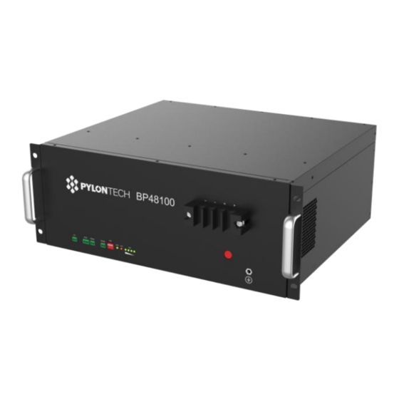
Structure and Parameter 2.1 Equipment Structure 2.1.1 Equipment Model BP4850 BP48100... -
Page 10: Equipment Front Interface Instruction
45kg 2.1.2 Equipment Front Interface Instruction This section details the front panel of the interface functions. Figure 2-1 Sketch of BP series Product Front Interface Power Port (1) Power cord connection: the same function of two power interface in parallel. - Page 11 RS485 A/B port (No. 3, Figure 2-1): when using multiple batteries in parallel, cascade each RS485 interface, information of other packs can be checked from the main pack. The definition of main battery and others please check “ADD Switch Table 2-3." ADD Switch (7) ADD Switch: 4 ADD switches, to definite different address code for each ...
- Page 12 LED Status Indicators (8) RUN Lamp (No.6 Figure 2-1): green, long lighting when charging and flash when discharging; ALM Lamp (No. 7 Figure 2-1 7): red, flashes when alarm and long bright if equipment failure or protected; Battery capacity indicator (No. 8 Figure 2-1): 4 green lamps, each light ...
-
Page 13: Battery Management System(Bms
2.2 Battery Management System(BMS) 2.2.1 Voltage Protection Low Voltage Protection in Discharge: When discharging, the protection starts if any one of the single cells has lower voltage than the setting value and the power supply stop. When voltages of all single cells return to the normal, protection removed. -
Page 14: Charge Parameters
If short circuit occurs, the system starts short circuit protection and lasts 30 seconds. Automatic Shutdown: The system will shutdown automatically after 10 hours without power supply 2.3 Charge Parameters When the device working, reasonable charge voltage you should set, recommended charge voltage range shown in Table 2-5. -
Page 15: Installation And Configuration
Installation and Configuration 3.1 Installation Preparation Safety Requirements Only those who have finished training and knowledge and fully grasp the power system personnel may install the system. During installation process, one must always observe the safety requirements listed below and local safety regulations. All the circuit under 48V connected to the external power supply system must ... -
Page 16: Environmental Requirements
Figure 3-1 Schematic of Installation Process Operation Environment Checking Environment Environmental Passed or Rectify and Checking Report Reform Tools and Materials Technical Preparation Unpacking Report Unpacking Project Coordination Ending 3.1.1 Environmental Requirements Ambient Temperature: -10℃~+50℃ Relative Humidity:5%~93% RH Altitude: Under 4000m Working environment: No conductive dust and corrosive gas... -
Page 17: Tools And Information
3.1.2 Tools and Information Hardware Tools and instruments are shown in Table 3-1: Table 3-1 Tools and Meters Name Screwdriver (Slotted, Phillips) Multimeter Wrench Clip-on Ammeter Diagonal Pliers Insulating Tape Pliers Thermometer Clip Pliers Antistatic Wrist Ring Strippers Ties Technical Information "Project Exploration Station Report", "Extra series lithium iron phosphate Standby Power User's Manual"... -
Page 18: Unpacking
mentioned in Table 2-6. 2. Switching Power Supply If the battery is connected to switching power supply, it must be confirmed the positive and negative switching power connector, and measure whether the output voltage meets the requirements in Table 2-5; and also recognizing the maximum operating current of the battery-powered load devices must be less than the maximum discharge current related products in Table 2-6. -
Page 19: Equipment Installation
Specifications of Power Cord. Power cord should meet the requirements of maximum discharge current of each product; Installation Space and Load-bearing To ensure there is enough space for installation, and sufficient load-bearing capacity for battery cabinet and brackets. Wiring ... -
Page 20: Electrical Installation
1 Tab Installation There are tabs and mounting accessories equipment box. Before the equipment fixed, install tabs on both sides of the device, and confirm screws are tightly connected. 2 Equipment Installation Extra 2000 products using 19-inch rack-mountable, it can be installed in the chassis designed with battery, and also be installed in the cabinet. - Page 21 cable is available. Anode and cathode: after power cord connected, the battery positive and negative should be connected respectively positive and negative of equipment. Cables connection order: 1 Ground Cable Connect one side of the cable to the copper rafts to ground, and the other side connect to the hole placed on right interface back of battery chassis with 4mm line connection, make sure connections are tight and well grounded.
- Page 22 When connect load, connect the user equipment side power line interface first, and then the battery power supply interface. (1) Connection of battery and the load device in DC backup power interface If the load device has a DC backup power interface, this installation can be used. Single load equipment: the power cord directly connected to the load equipment DC backup power interface.
- Page 23 Note: Confirm the positive and negative of switching power supply before connecting, the red power wire to positive and black one to negative; Before connecting, verify the charging parameters of interface switching power supply battery. Voltage and current should satisfy charging parameters in Table 2-5 Battery.
- Page 24 5 Communication Interface Connection If using the local network, put the specially equipped RS232 communication cable to connect the battery and computer serial RS232 interface. If multiple network cascade battery, connect the battery RS232 interface with ADD Address is 1. 6 Powering on Device After completing these steps, turn on power to the entire system to activate the battery, installation completed.
-
Page 25: Using, Maintenance And Troubleshooting
Using, Maintenance and Troubleshooting 4.1 Alarm Description and Processing When protection start or failure, the ALM indicator on the front panel will alarm, through net management can query specific alarm class and take appropriate action. 4.1.1 The Alarm and Countermeasure Influence System Output Please follow Table 4-1 processing if output of the fault appears such as over-voltage, charge over-current, under-voltage protection, high-temp protection and other abnormalities. -
Page 26: Common Fault Analysis And Solutions
should inspect equipment according to prompt information, and determine the fault type and location, and take appropriate measures to ensure the system is in the best working condition, not to affect the system output. Phenomenon and countermeasures are shown in Table 4-2. Table 4-2 Secondary Alarm Category Alarm Indication... - Page 27 Pylon Technologies Co., Ltd. No. 73, Lane 887, ZuChongzhi Road, Zhangjiang Hi-Tech Park Pudong, Shanghai 201203, China +86-21-51317699 | +86-21-51317698 service@pylontech.com.cn www.pylontech.com.cn...
Need help?
Do you have a question about the BP Series and is the answer not in the manual?
Questions and answers