Table of Contents
Advertisement
Quick Links
Advertisement
Table of Contents

Related Manuals for Cognex In-Sight VC200

Summary of Contents for Cognex In-Sight VC200
- Page 1 ® In-Sight VC200 Vision System Reference Guide 08/08/2016 Version: 7.0.0.131...
-
Page 2: Legal Notices
Copyright © 2016. Cognex Corporation. All Rights Reserved. Portions of the hardware and software provided by Cognex may be covered by one or more U.S. and foreign patents, as well as pending U.S. and foreign patents listed on the Cognex web site at: http://www.cognex.com/patents. -
Page 3: Symbols
Symbols Symbols The following symbols indicate safety precautions and supplemental information. WARNING: This symbol indicates the presence of a hazard that could result in death, serious personal injury or electrical shock. CAUTION: This symbol indicates the presence of a hazard that could result in property damage. Note: Notes provide supplemental information about a subject. -
Page 4: Regulations/Conformity: Vision Controller
Regulations/Conformity: Vision Controller Regulations/Conformity: Vision Controller Note: For the most up-to-date regulations and conformity information, please refer to the Cognex online support site: http://www.cognex.com/Support. Safety and Regulatory Cognex Corporation Manufacturer One Vision Drive Natick, MA 01760 USA Regulatory Model 1AAL FCC Part 15, Class A This device complies with Part 15 of the FCC Rules. -
Page 5: Regulations/Conformity: In-Sight Cameras
Regulations/Conformity: In-Sight Cameras Regulations/Conformity: In-Sight Cameras Note: For the most up-to-date regulations and conformity information, please refer to the Cognex online support site: http://www.cognex.com/Support. Safety and Regulatory Cognex Corporation Manufacturer One Vision Drive Natick, MA 01760 USA ISC-8402: Regulatory Model 1AAW... -
Page 6: Precautions
The vision controller is intended to be supplied by a NRTL listed power supply with a minimum output rated 24VDC, 3.5A and must be used with the Cognex-supplied 24VDC power connector. Any other voltage creates a risk of fire or shock and can damage the components. Wire and connections must be in accordance with these instructions, the National Electrical Code and applicable national and local wiring standards and rules. -
Page 7: Open Source Libraries
Open Source Libraries Open Source Libraries ® The In-Sight VC200 vision controller uses third-party open source software, whose licenses are described in the click- accept agreement that is part of the In-Sight VC Explorer software installation. -
Page 8: Table Of Contents
Table of Contents Table of Contents Legal Notices Symbols Regulations/Conformity: Vision Controller Regulations/Conformity: In-Sight Cameras Precautions Open Source Libraries Table of Contents Introduction Support Standard Components Accessories Cables Vision Controller Connectors and Indicators Camera Connectors and Indicators Installation Mount the Vision Controller Use the Accessory Wall Mounting Brackets Use the Accessory DIN Rail Mounting Bracket Install the Camera... - Page 9 Table of Contents ISC-8405 Dimensions ISC-8405 Dimensions (with Accessory Mounting Block) Wire Inputs and Outputs Input from PLC - Current Sinking Input from PLC - Current Sourcing Output to PLC - Current Sinking Output to PLC - Current Sourcing Output to Pilot Light - Current Sinking Output to Pilot Light - Current Sourcing Cleaning/Maintenance Cleaning the Vision Controller...
-
Page 10: Introduction
Support for current sinking (NPN) and current sourcing (PNP) devices. DIN-rail mountable. Support Several resources are available to assist you in using the vision controller with the connected Cognex device: ® The In-Sight VC Explorer User Guide, included with In-Sight VC Explorer software. -
Page 11: Standard Components
The vision controller is shipped with the components listed below. Note: If any of the standard components appear to be missing or damaged, immediately contact your Cognex Authorized Service Provider (ASP) or Cognex Technical Support. The number and type of cameras included with the vision controller will vary based on the product kit. -
Page 12: Accessories
Introduction Accessories The following components can be purchased separately. For a complete list of options and accessories, contact your local Cognex sales representative. Component Description Wall Mounting Bracket Bracket for wall-mounting the vision controller. (BKT-WALL-VC200-01) DIN Rail Mounting Bracket for mounting the vision controller to a 35x15mm DIN rail. - Page 13 Introduction Ethernet Cable (ISC-8402) The RJ-45 to M12 X-coded Ethernet cable provides Gigabit Ethernet connectivity and supplies power to the camera. The pin-outs for the cable are listed in the Ethernet Cable Specifications (ISC-8402) on page 44. This cable is available in the lengths and styles listed below.
-
Page 14: Vision Controller Connectors And Indicators
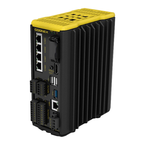
Introduction Vision Controller Connectors and Indicators Connector/Indicator Function The four CAM ports (CAM 0 - CAM 3) are RJ-45 ports that provide Ethernet connectivity CAM Ports and Power over Ethernet (PoE) to In-Sight cameras. The green LED is solid when the and LEDs connected camera is running at 1000 Mbps;... - Page 15 Introduction Connector/Indicator Function SD Card Slot The SD card slot is used to save images, run time files and results. LEDs PWR LED: The green PWR LED illuminates to indicate that the vision controller is powered on. LED1: Green when active. User configurable. LED2: Red when active.
-
Page 16: Camera Connectors And Indicators
Introduction Camera Connectors and Indicators ISC-8402 ISC-8405 Connector/Indicator Description 1000-BaseT: LED turns on when the camera is receiving power during startup, and blinks ENET LED green once network traffic is detected. 100-BaseT: LED turns on when the camera is receiving power during startup, and blinks green and red (appears orange) once network traffic is detected. -
Page 17: Installation
Note: The vision controller may be optionally mounted using the accessory wall mounting bracket (BKT-WALL- VC200-01) or to a 15mm DIN rail, using the accessory DIN rail mounting bracket (BKT-DIN-VC200-01). The DIN rail mounting bracket accessory is not suitable for a 7.5mm profile DIN rail. Please contact your Cognex sales representative for more information. -
Page 18: Use The Accessory Wall Mounting Brackets
Installation Use the Accessory Wall Mounting Brackets The accessory wall mounting bracket kit (BKT-WALL-VC200-01) includes two wall mounting brackets and M4 screws (quantity 4) to secure the controller to a mounting surface. CAUTION: The vision controller must be mounted in a vertical orientation with the top of the controller up, and cannot be mounted in a horizontal orientation. -
Page 19: Use The Accessory Din Rail Mounting Bracket
Installation Use the Accessory DIN Rail Mounting Bracket The accessory DIN rail mounting bracket kit (BKT-DIN-VC200-01) includes the DIN rail bracket and M4 screws (quantity 4) to secure the controller to a 35x15mm DIN rail. Note: The DIN rail mounting bracket accessory is not suitable for a 7.5mm profile DIN rail. CAUTION: The vision controller must be mounted in a vertical orientation with the top of the controller up, and cannot be mounted in a horizontal orientation. -
Page 20: Install The Camera
Installation Install the Camera The following sections provide steps for installing the camera and connecting it to the vision controller. Mount the Camera The camera provides mounting holes for attachment to a mounting surface. Note: For the mounting holes closest to the lens opening, the thread length of the M3 screw should not exceed 4.5mm. -
Page 21: Install The Lens
Installation Install the Lens 1. Remove the protective film covering the threaded lens opening, if present. 2. Attach a C-Mount lens to the camera. The exact lens focal length needed depends on the working distance and the field of view required for your machine vision application. Connect the Breakout Cable (Optional) The camera's I/O connector provides access to the STROBE and COMMON lines on the camera. - Page 22 Installation 3. Connect the STROBE (White) and COMMON (Gray) wires to a strobe device. For more information, refer to Breakout Cable Specifications on page 43.
-
Page 23: Connect The Ethernet Cable
Cognex recommends only cold-plugging the camera; turn the vision controller power off when connecting or disconnecting the camera. The Ethernet cable must be shielded. For the ISC-8405 camera, Cognex strongly recommends Cat 6 or Cat 7 Ethernet cables with S/STP shielding. -
Page 24: Connect The Inputs And Outputs Terminal Blocks
Installation Connect the INPUTS and OUTPUTS Terminal Blocks The vision controller is shipped with four terminal blocks for connecting inputs and outputs. Note: It is recommended that all terminal blocks be installed to the vision controller, even if no devices are wired to the terminal block connectors. -
Page 25: Connect To An Ethernet Network
Cognex recommends only cold-plugging the HDMI cable and display; turn the vision controller power off when connecting or disconnecting the HDMI cable. Note: To avoid electromagnetic interference, the HDMI cable must be shielded. A shielded Cognex accessory HDMI cable (P/N 300-10006-xR) is available for purchase separately. -
Page 26: Connect Usb Devices (Optional)
If connecting a USB mouse, keyboard or storage device to the vision controller, connect the USB device to one of the vision controller's USB ports. CAUTION: Cognex recommends only cold-plugging USB devices; turn the vision controller power off when connecting or disconnecting USB devices. Note: When using the vision controller in an electrically noisy environment, it is important to use USB devices that are rated for industrial use in the same environment. - Page 27 Installation 3. Insert the power supply's +24VDC (Power) wire to Pin 1 and the -24VDC (Return) wire to Pin 2 on the power connector. Connect a frame ground wire from Pin 3 to frame ground. Recommended wiring is 14 - 18 AWG, solid or stranded wire.
-
Page 28: Specifications
The following sections list general specifications for the vision controller and cameras. Vision Controller Specifications Specifications Vision Controller Supported ISC-8402 and ISC-8405 cameras. Cognex Devices Program 8GB non-volatile flash memory. Unlimited storage via remote network device. Memory Image 2GB SDRAM. - Page 29 Specifications Specifications Vision Controller Operating 0°C to 45°C (32°F to 113°F) Temperature Storage -30°C to 80°C (-22°F to 176°F) Temperature Humidity 10% - 85%, non-condensing (Operating and Storage) Altitude 2,000m (6565ft) Protection IP30 Shock 30 G, per IEC 60068-2-7EA. (Storage and Shipment) Vibration 2 G, 2 hrs/axis (10-500 Hz) per IEC 60068-2-6, FC.
-
Page 30: Inputs
Specifications Inputs The vision controller features eight independent inputs (INPUTS 0 - 7), which can be used to trigger vision controller events. The inputs are optically isolated and typically connected (directly or indirectly) to a PLC or photoelectric sensor. The vision controller will respond to an event when the voltage difference between the INPUT and INPUT COMMON exceeds 10VDC. -
Page 31: Outputs
Specifications Outputs The vision controller features sixteen independent outputs (OUTPUTS 0 -15), which are optically isolated. OUTPUTS 0 - 7 provide up to 50mA current (maximum). These outputs are typically connected (directly or indirectly) to an input, such as a trigger input or PLC input. OUTPUTS 8 - 15 provide up to 100mA of current (maximum). -
Page 32: Port And Terminal Block Specifications
Specifications Port and Terminal Block Specifications The following sections provide specifications for the vision controller's ports and terminal blocks. CAM Ports The four CAM ports (CAM 0 - CAM 3) are RJ-45 ports that provide Ethernet connectivity and Power over Ethernet (PoE) to In-Sight cameras. - Page 33 Specifications VIDEO OUT Port The VIDEO OUT port is a locking HDMI port that provides connection to a display device. Pin Number Signal Name D2 + D2 - Shield D2 - D1 + D1 - Shield D1 - D0 + D0 - Shield D0 - CLK + CLK Shield...
- Page 34 Specifications USB 2.0 Ports The two USB 2.0 ports can be used to connect mouse, keyboard or mass storage device. Pin Number Signal Name USB 3.0 Port The USB 3.0 port can be used to connect mouse, keyboard or mass storage device. Pin Number Signal Name VBUS...
- Page 35 Specifications INPUTS Terminal Block Assignments The INPUTS terminal blocks provide access to a total of 8 inputs and 2 common connections. Recommended wiring is 16 - 26 AWG, solid or stranded wire. CAUTION: The maximum torque that can be applied to the I/O terminal connectors is 0.25 Nm (2.2 in-lb). Applying torque above this limit can damage the connectors.
- Page 36 Specifications OUTPUTS Terminal Block Assignments The OUTPUTS terminal blocks provide access to a total of 16 outputs and 2 common connections. Recommended wiring is 16 - 26 AWG, solid or stranded wire. CAUTION: The maximum torque that can be applied to the I/O terminal connectors is 0.25 Nm (2.2 in-lb). Applying torque above this limit can damage the connectors.
- Page 37 Specifications 24VDC Power Connector Terminal Assignments The 24VDC power connector is used to connect an external power supply to the vision controller. Recommended wiring is 14 - 18 AWG, solid or stranded wire. CAUTION: The maximum torque that can be applied to the 24VDC power connector is 0.6 Nm (5.3 in-lb). Applying torque above this limit can damage the connector.
-
Page 38: Hdmi Cable Specifications
Specifications HDMI Cable Specifications The shielded HDMI cable provides connection to a display device. P1 Pin Number Signal Wire Color P2 Pin Number D2 + White D2 - Brown D2 - Shield Drain D1 + White D1 - D1 - Shield Drain D0 + White... -
Page 39: Vision Controller Dimensions
Specifications Vision Controller Dimensions Note: All dimensions are in millimeters [inches] and are for reference purposes only. All specifications are for reference purpose only and may be changed without notice. -
Page 40: Camera Specifications
Specifications Camera Specifications Specifications ISC-8402 ISC-8405 Image Processing 512MB SDRAM Memory Sensor Type 1/1.8 inch CMOS, global shutter 1/2.5 inch CMOS, rolling shutter Sensor Properties 9mm diagonal, 4.5 x 4.5µm sq. pixels 7.13mm diagonal, 2.2 x 2.2µm sq. pixels Maximum Resolution 1600 x 1200 2592 x 1944 (pixels) - Page 41 Specifications Specifications ISC-8402 ISC-8405 Protection IP40 with cables and lens attached. IP30 with cables and lens attached. Shock (Shipping and IEC 60068-2-27: 18 shocks (3 shocks in each polarity in each (X, Y, Z) axis) 80 Gs (800 m/s2 Storage) at 11 MS, half-sinusoidal) Vibration (Shipping IEC 60068-2-6: vibration test in each of the three main axis for 2 hours @ 10 Gs (10 to 500 Hz...
-
Page 42: Strobe Output
Specifications Strobe Output The camera features one built-in strobe output, which is optically isolated. The strobe output can be used as either an NPN (current sinking) or PNP (current sourcing) line. Specification Description Voltage 28VDC maximum through external load. Current 100mA maximum sink current. -
Page 43: Breakout Cable Specifications
Specifications Breakout Cable Specifications The camera's Breakout cable can be connected to a strobe light. The Breakout cable is not terminated. P1 Pin Number Signal Wire Color UNUSED Brown STROBE White UNUSED Blue UNUSED Black COMMON Gray Note: Cables are sold separately. Unused bare wires can be clipped short or tied back using a tie made of non-conductive material. -
Page 44: Ethernet Cable Specifications (Isc-8402)
Specifications Ethernet Cable Specifications (ISC-8402) The RJ-45 to M12 X-coded Ethernet cable provides Ethernet connectivity and supplies power to the camera. P1 Pin Number Wire Color Signal Name P2 Pin Number White/Orange TxRx A + Orange TxRx A - White/Green TxRx B + Blue TxRx C +... -
Page 45: Ethernet Cable Specifications (Isc-8405)
Note: Cables are sold separately. CAUTION: The Ethernet cable must be shielded. For the ISC-8405 camera, Cognex strongly recommends Cat 6 or Cat 7 Ethernet cables with S/STP shielding. The Ethernet cable shield must be grounded at the far end. -
Page 46: Isc-8402 Dimensions
Specifications ISC-8402 Dimensions Note: All dimensions are in millimeters [inches] and are for reference purposes only. All specifications are for reference purpose only and may be changed without notice. -
Page 47: Isc-8402 Dimensions (With Accessory Mounting Block)
Specifications ISC-8402 Dimensions (with Accessory Mounting Block) Note: All dimensions are in millimeters [inches] and are for reference purposes only. All specifications are for reference purpose only and may be changed without notice. -
Page 48: Isc-8405 Dimensions
Specifications ISC-8405 Dimensions Note: All dimensions are in millimeters [inches] and are for reference purposes only. All specifications are for reference purpose only and may be changed without notice. -
Page 49: Isc-8405 Dimensions (With Accessory Mounting Block)
Specifications ISC-8405 Dimensions (with Accessory Mounting Block) Note: All dimensions are in millimeters [inches] and are for reference purposes only. All specifications are for reference purpose only and may be changed without notice. -
Page 50: Wire Inputs And Outputs
Wire Inputs and Outputs Wire Inputs and Outputs The following figures show basic wiring for some of the more common I/O configurations. Input from PLC - Current Sinking To configure the input as a sinking input, connect INPUT COMMON (for example, C1) to the high voltage reference (+24VDC) and connect one of the INPUTS on the same terminal row (for example, INPUT 0) to the OUTPUT of the photoelectric sensor or PLC. -
Page 51: Input From Plc - Current Sourcing
Wire Inputs and Outputs Input from PLC - Current Sourcing To configure the input as sourcing input, connect INPUT COMMON (for example, C1) to the low voltage reference (24V COMMON) and one of the INPUTS on the same terminal row (for example, INPUT 0) to the OUTPUT of the photoelectric sensor or PLC. -
Page 52: Output To Plc - Current Sinking
Wire Inputs and Outputs Output to PLC - Current Sinking To configure the output as a sinking output, connect OUTPUT COMMON (for example, C1) to the low voltage reference (24V COMMON) and connect one of the OUTPUTS on the same terminal row (for example, OUTPUT 4) to the INPUT of the PLC. -
Page 53: Output To Plc - Current Sourcing
Wire Inputs and Outputs Output to PLC - Current Sourcing To configure the output as a sourcing output, connect OUTPUT COMMON (for example, C1) to the high voltage reference (+24VDC) and connect one of the OUTPUTS on the same terminal row (for example, OUTPUT 4) to the INPUT of the PLC. -
Page 54: Output To Pilot Light - Current Sinking
Wire Inputs and Outputs Output to Pilot Light - Current Sinking To configure the output as a sinking output, connect OUTPUT COMMON (for example, C2) to the power supply's low voltage reference (24V COMMON) and connect one of the OUTPUTS on the same terminal row (for example, OUTPUT 12) to the pilot light's low voltage reference (24V COMMON). -
Page 55: Output To Pilot Light - Current Sourcing
Wire Inputs and Outputs Output to Pilot Light - Current Sourcing To configure the output as a sourcing output, connect OUTPUT COMMON (for example, C2) to the power supply's high voltage reference (+24VDC) and connect one of the OUTPUTS on the same terminal row (for example, OUTPUT 12) to the pilot light's high voltage reference (+24VDC). -
Page 56: Cleaning/Maintenance
Cleaning/Maintenance Cleaning/Maintenance Cleaning the Vision Controller Use a cleaning cloth or brush to remove dirt, dust and smudges from the vision controller. Keep all liquids away from the vision controller connectors and openings. CAUTION: Cleaning chemicals should not be used on the vision controller. Clean the Camera Housing To clean the outside of the camera housing, use a small amount of mild detergent cleaner or isopropyl alcohol on a cleaning cloth.
Need help?
Do you have a question about the In-Sight VC200 and is the answer not in the manual?
Questions and answers