Table of Contents
Advertisement
Advertisement
Table of Contents

Summary of Contents for Panametrics XMO2
- Page 1 XMO2-IDM User’s manual 910-141 Rev. G...
- Page 2 ATTENTION! This manual should be used only for XMO2 units with the IDM User Program (Option D = 3 or 4). For XMO2 units with the Terminal User Program (Option D = 1 or 2), manual number 910-141A must be used.
- Page 3 XMO2-IDM Oxygen analyzer User’s manual 910-141 Rev. G March 2015...
- Page 4 [no content intended for this page]...
-
Page 5: Information Paragraphs
WARNING! This symbol indicates a risk of potential serious personal injury, unless these Waste Electrical and Electronic Equipment (WEEE) directive instructions are followed carefully. Panametrics is an active participant in Europe’s Waste Electrical and Electronic Equipment (WEEE) take-back initiative, directive 2012/19/EU. Safety issues... -
Page 6: Table Of Contents
3.2 Powering Up the XMO2 transmitter ........ - Page 7 3.7 Required calibration materials ..............16 3.8 Preparing for field calibration .
- Page 8 D.4 Adding the XMO2 ........
-
Page 9: Chapter 1. Features And Capabilities
• The measurement cell design is resistant to oxygen. contamination and relatively tolerant of sample gas flow rate variations. As it has no moving parts, the XMO2 As its magnetic susceptibility is approximately 100 times performs reliably under the shock and vibration found in greater than that of most other common gases, oxygen many industrial applications. - Page 10 thermistors. One thermistor of each pair located inside the the magnetic field, causing the sample gas pressure to magnetic field and the other thermistor of each pair located become locally higher in the center of the chamber. At the outside the field. Because the thermistors are electrically same time, the sample gas pressure is slightly lower near heated, a temperature gradient is thus created within the the thermistors because the high thermistor temperature...
- Page 11 To compensate for such variations, the amplified and converted to a 4-20 mA analog output that XMO2 has a unique “bridge-within-a-bridge” design. is proportional to the concentration of oxygen in the gas The oxygen measuring bridge circuit described on the mixture.
-
Page 12: System Components
RS232 digital output to external devices 24 VDC power input @1.2 A maximum at power-up, and it The XMO2 is designed to be installed in a sample system as provides a 4-20 mA analog output signal that is proportional close as possible to the process sample point. It is available... -
Page 13: The Sample System
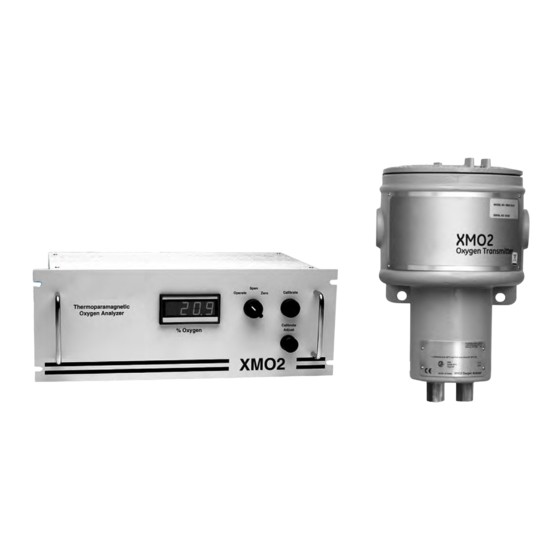
The XMO2 transmitter, which is shown in Figure 4 on page 4, IMPORTANT: can be configured for the following standard oxygen ranges: ATEX compliance requires both: 0 to 1% 0 to 25% • Fast Response calibration of the XMO2 transmitter. -
Page 14: Chapter 2. Installation
You can order a complete sample system from Panametrics and its sample system. It also contains information on that is mounted on a steel panel and includes the XMO2 connecting optional system components. Installation of the transmitter and all necessary components and plumbing. -
Page 15: Wiring The Xmo2 Transmitter
This section describes how to make all necessary electrical CAUTION! connections to the XMO2 system. Always apply power to the XMO2 transmitter immediately after installation, especially if it is mounted outdoors or in a humid area. Figure 5: Basic XMO2 sample system (ref. dwg #732-164) -
Page 16: Ce Mark Requirements
The XMO2 transmitter enclosure must be cables must be grounded and shielded as properly grounded. described in Appendix E. Connect the external ground screw on the XMO2 enclosure (see Figure 6 below) to a suitable earth ground. Figure 6: XMO2 Ground screw locations... -
Page 17: Cable Specifications
Panametrics cables described above. 2.3.5 Accessing terminal blocks TB1 and TB2 If you are using your own cable to wire the XMO2, refer to Table 2 below for cable requirements. The 24 VDC power input, 4-20 mA analog output, and RS232... - Page 18 Figure 7: TB1 and TB2 terminal block connections Proceed to the next section to begin making connections to terminal blocks TB1 and TB2.
-
Page 19: Wiring The Signal Connections
With both the XMO2 and the computer turned OFF, Connect the 24 VDC input power leads as follows: connect a serial cable from the XMO2 to the PC. See Chapter 2, Installation, for detailed instructions. CAUTION! -
Page 20: Connecting To Other Devices
Connecting to other devices system solenoids for automatic zero and span calibration of the XMO2. See Figure 74 on page 59 for an interconnection diagram, and refer to the TMO2D User’s Manual (910-084) for This section discusses interconnection of the XMO2 details on its operation. -
Page 21: Chapter 3. Startup And Operation
XMO2 system. The following specific topics Set the sample system ball valves to direct only the discussed: sample inlet stream to the inlet port of the XMO2 transmitter. • Powering up the XMO2 transmitter Use the sample inlet needle valve to regulate the flow of •... -
Page 22: Analog Output Calibration Options
To perform this task, either of the following * Pressure compensation is required procedures may be used: In addition, your XMO2 was calibrated at the factory for the • Pushbutton calibration (offset gas method) compensation signal specified at the time of purchase. The following standard compensation signals are provided: •... - Page 23 Figure 9: Sample calibration sheet...
-
Page 24: Enhancing The Factory Calibration
To prepare the XMO2 for a field calibration, refer to Figure 10 on page 17 and perform the following preliminary steps: To maintain the integrity of this process, the XMO2 should be recalibrated periodically. - Page 25 Figure 10: XMO2 Cover, set screw, and PCB Note: The XMO2 digital PCB (see Figure 11 below) is located directly below the cover (see Figure 10 above) Figure 11: PCB calibration switches CAUTION! Switch S2, jumper P6, potentiometer R24, and potentiometer R25 are also located on the XMO2 circuit boards.
-
Page 26: One-Gas Pushbutton Field Calibration
Using the sample system controls, stop the flow of sample Calibration Pushbutton and hold it down for 20 seconds. gas to the XMO2 inlet port and initiate a flow of the same During this time, the green light below the Calibration zero gas specified on the XMO2 Calibration Sheet. -
Page 27: Span Gas Pushbutton Calibration
Using the sample system controls, stop the flow of five commands displayed in Figure 12 below. To access any sample gas to the XMO2 inlet port and initiate a flow of of the commands, simply select it from the menu. -
Page 28: The Field Cal Menu
Figure 15 below opens. Figure 13: Field cal window The Field Cal option offers the following five choices: • Perform Cal - calibrates the XMO2 • Configure Cal - sets the calibration type and parameters •... - Page 29 The above menu is used to specify the oxygen percentages of the zero and span calibration gases that will be used. The Figure 17: Configure cal window recommended gases are listed on the XMO2 Calibration Click on the desired option button and proceed to the Data Sheet.
-
Page 30: Calibration Drifts
3.13.2c Before delay time Clicking on the Before Delay Time button opens a window similar to Figure 21 below. Figure 23: Max total drift entry window Enter the desired percentage of the full-scale reading in the text box, and click the Next Item/Enter button to confirm the entry (click the Previous Item or Exit Page button to leave the Figure 21: Before delay time window window without changing the existing percentage). -
Page 31: Clear Calibration
The window for the Clear Calibration option is similar to Figure 25 below. The XMO2 Calibration Sheet shipped with the unit lists the 4-20 mA analog output range that was set at the factory. IDM enables you to change this range via the 4-20mA Output option. - Page 32 3.14.1 4-20mA range 3.14.2 4mA Cal Selecting the 4-20mA Range option opens a window similar Click on the 4mA Cal button to open a window similar to to Figure 28 below. Figure 30 below and force the analog output to exactly 4.00 mA.
-
Page 33: 4-20Ma Test
3.14.4 4-20mA test 3.14.5 %O2 test Selecting the 4-20mA Test option opens a window similar to Selecting the %O2 Test option opens a window similar to Figure 32 below. Figure 33 below. Figure 33: %O2 test window Figure 32: 4-20mA test window Enter an oxygen percentage in the text box. - Page 34 [no content intended for this page]...
-
Page 35: Chapter 4. Programming With Instrument Data Manager
4.2 The edit functions menu Figure 35: Error handler window To access the XMO2 calibration, pull down the Edit Functions menu from the Instrument window.The menu consists of the There is a button in the above window for each of the five commands displayed in Figure 34 below. -
Page 36: Total Drift Error
Figure 38 below opens. Figure 39: BKGD comp window Note: If background gas compensation is not required for your XMO2, click on the No button in the above window and proceed directly to the Pressure Compensation section on the next page. -
Page 37: Pressure Compensation
Figure 42 below opens. Figure 42: Pressure comp window Note: If pressure compensation is not required for your XMO2, click on the No button in the above window and proceed directly to the Entering Data Points section on page 51. - Page 38 Entering data points 4.3.2b Pressure #1 background gases In the window shown in Figure 45 on page 30, click on the Note: If you are not using background gas compensation, Background Label 1 button (the actual text on this button will this menu does not appear.
-
Page 39: The Advanced Menu
• Fast Response - a software enhancement resulting in faster performance under certain conditions • Language - change the language used for the XMO2 menus • Meter ID - change the meter identification number To select one of the above options, click on the corresponding button in the window above and proceed to the appropriate section for instructions. -
Page 40: Fast Response
Figure 53: Language window to Figure 52 below opens. The standard language used for the XMO2 menus is English, and these strings are stored in a meter file called default.txt. If you wish to translate this file into another language, click on the Upload to PC button, and a window similar to Figure 54 below opens. -
Page 41: Meter Id
In the above window, navigate to the location and name of main menu. your translated menu string file on the PC and click on the OK button. The new file will be loaded into the XMO2. After IMPORTANT: you power down the meter and restart it, all of the menus Once you have entered a new meter ID number, you will be displayed in the new language. - Page 42 Your assigned password is: 2719. [Please copy this page and keep it in a safe place for future reference.]...
-
Page 43: Chapter 5. Specifications
Chapter 5. Specifications Performance ±1% of span Accuracy ±2% of span for 0 to 1% range ±0.2% O for 90 to 100% and 80 to 100% Linearity ±0.5% of span Repeatability ±0.2% of span Measurement Resolution 0.01 mA Zero: ±1.0% of span per month (±2% of 0-1% O range) Stability Span: ±0.4% of span per month (±0.8% for 0-1% O... -
Page 44: Functional Specifications
Lloyd’s Registry approval Note: For CE compliance, the power and I/O cables must be shielded. All cables must be terminated within the cable gland at the XMO2. Note: See the Certification Drawings in Appendix B, Outline and Installation Drawings, for... -
Page 45: Optional Accessories
5.4 Optional accessories Panametrics offers a complete line of optional accessories for use with the XMO2 transmitter. These include: • PS5R-C24: 24 VDC power supply • X4(*): 4-conductor cable for power input and analog output connections (* specifies length in feet) lengths up to 450 ft (137 m) are available •... -
Page 46: Calibration Specification
4 - 0-10% 5 - 0-21% 6 - 0-25% 7 - 0-50% (atmospheric pressure compensation XMO2 hardware required) 8 - 0-100% (atmospheric pressure compensation XMO2 hardware required) A - 90-100% (atmospheric pressure compensation XMO2 hardware required) B - 80-100% (atmospheric pressure compensation XMO2 hardware required) -
Page 47: A Calibration Sheet
5.7 A calibration sheet For reference, a sample Calibration Sheet for the XMO2 transmitter is shown in Figure 58 below. Figure 58: Sample XMO2 calibration sheet... -
Page 48: Appendix A. Two Typical Applications
Appendix A. Two typical applications A.1 Blanketing gases in hydrocarbon liquid storage tanks The XMO2 transmitter and its associated sample system is often used to measure the concentration of oxygen (O ) in the nitrogen (N ) or carbon dioxide (CO ) gases used to blanket hydrocarbon liquids during storage. -
Page 49: Basic Operating Procedure
• Automatic calibration gas solenoid valves for the The XMO2 is recalibrated periodically using the purge gas automatic calibration of the system on a timed basis to zero the instrument and ambient air (20.93% O ) to span •... -
Page 50: Reactor Feed Gases In Formaldehyde Production
A.2 Reactor feed gases in formaldehyde production The XMO2 transmitter and its associated sample system is often used to measure the concentration of oxygen (O ) in an air/ methanol (CH3OH) vapor mixture that is commonly used as a reactor feed gas in the production of formaldehyde. -
Page 51: Basic Operating Procedure
) is used as the source of O , and the air/CH required extensive maintenance and frequent manual vapor mixture is sampled at the reactor inlet. The XMO2 calibration. In addition, the sensors were easily damaged by continuously verifies that the optimal amount of O (typically condensable liquids, requiring frequent sensor replacement. -
Page 52: Appendix B. Outline And Installation Drawings
Appendix B. Outline and installation drawings This appendix includes the following XMO2 drawings in 11” x 17” fold-out format: • Figure 61, “Certification Drawing (ref. dwg #752-168, Rev. E, SH1)” on page 46 • Figure 62, “Certification Drawing (ref. dwg #752-168, Rev. E, SH2)” on page 47 •... - Page 53 [no content intended for this page]...
- Page 54 Appendix B. Outline and installation drawings Figure 61: Certification drawing (ref. dwg #752-168, Rev. E, SH1)
- Page 55 Appendix B. Outline and installation drawings Figure 62: Certification drawing (ref. dwg #752-168, Rev. E, SH2)
- Page 56 Appendix B. Outline and installation drawings Figure 63: Certification drawing (ref. dwg #752-168, Rev. E, SH3)
- Page 57 Appendix B. Outline and installation drawings Figure 64: RS232 Digital output cables...
- Page 58 Appendix B. Outline and installation drawings Figure 65: Digital PCB assembly (ref. dwg #703-1316, rev. K, sh.1)
- Page 59 Appendix B. Outline and installation drawings Figure 66: Digital PCB assembly (ref. dwg #703-1316, rev. K, sh. 2)
- Page 60 Appendix B. Outline and installation drawings Figure 67: Digital PCB schematic (ref. dwg #700-1316, rev. H, sh. 1)
- Page 61 Appendix B. Outline and installation drawings Figure 68: Digital PCB schematic (ref. dwg #700-1316, rev. H, sh. 2)
- Page 62 Appendix B. Outline and installation drawings Figure 69: Analog PCB assembly (ref. dwg #703-1276, rev. H,)
- Page 63 Appendix B. Outline and installation drawings Figure 70: Analog PCB schematic (ref. dwg #700-1276, rev. F, sh. 1)
- Page 64 Appendix B. Outline and installation drawings Figure 71: Analog PCB schematic (ref. dwg #700-1276, rev. F, sh. 2)
- Page 65 Appendix B. Outline and installation drawings Figure 72: EMI Filter PCB assembly (ref. dwg. #703-1550, rev. A)
- Page 66 Appendix B. Outline and installation drawings Figure 73: EMI Filter PCB schematic (ref. dwg. #700-1550, rev. A)
- Page 67 Appendix B. Outline and installation drawings Figure 74: Interconnection diagrams...
-
Page 68: Appendix C. Idm Menu Maps
Appendix C. IDM menu maps This appendix includes the following IDM menu maps: • Figure 75, “Field Cal, 4-20mA Output and Error Handler Menu Map,” on page 62 • Figure 76, “Factory Cal and Advanced Menu Map,” on page 63... - Page 69 [no content intended for this page]...
- Page 70 Appendix C. IDM menu maps Figure 75: Field Cal, 4-20mA Output and error handler menu map...
- Page 71 Appendix C. IDM menu maps Figure 76: Factory cal and advanced menu map...
-
Page 72: Appendix D. Programming With Panaview
Figure 78 below. communications between Windows-based PCs and Panametrics instruments compatible with IDM protocol, such as the XMO2 oxygen transmitter. [Compatible 32-bit Windows operating systems include Windows 98SE, NT 4.0 (with Service Pack 6), 2000, XP and ME.] With PanaView, you can: •... -
Page 73: Adding The Xmo2
D.4 Adding the XMO2 If the initialization is successful, the Meter Browser shows a listing similar to Figure 81 below. To add the XMO2 on the IDM-configured communications port, complete the following steps: Highlight the communication port to which the meter will be added by clicking on it, and then open the “Edit”... -
Page 74: Changing Meter Settings
To open a particular menu, double-click on that menu on the tree. For example, if you double-click on the Field Through PanaView, XMO2 users can handle remote Cal menu, a window opens similar to Figure 85 below. programming of the meter. They can: •... - Page 75 As you step through the menu, the bottom panel lists the current settings (modified or left unchanged), as shown in Figure 87 below. If you modify or step through more than five items, a scroll bar at the right of the panel lets you review the earlier settings.
-
Page 76: Appendix E. Ce Mark Compliance
Use shielded cable* to connect the line power and the 4-20mA analog output device to the XMO2. It is recommended to use Panametrics P/N X4(*) or equivalent for all weatherproof installation, and Panametrics P/N Power/Analog Output Z4(*) or equivalent for all explosion/flameproof installation. -
Page 77: Emi Filter Board
EMI filter board For CE compliance, an EMI filter board has been added to the XMO2 (see Figure 88 below). This board is connected internally to terminal block TB1. The power and analog output connections are now made to terminal block TB3 on the EMI filter board. -
Page 78: Wiring The Signal Connections For The Weatherproof Version
Install the first cable entry device in accordance with the manufacturer’s instructions. Note: If installation of the cable entry device is only partially complete, Panametrics recommends tagging the device to ensure the safety of subsequent users. Thread the cable gland entry body into the XMO2 port closest to the terminal blocks. -
Page 79: Wiring The Signal Connections For The Explosion/Flameproof Version
Unplug the TB2 connector by pulling it straight out of Remove the tab “Remove Before Installation”. its socket, and loosen the terminal screws on the TB2 Thread the cable gland entry body into the XMO2 connector. port closest to the terminal blocks. - Page 80 Insert the 3-wire cable TX (white) lead into pin TB2-2 Connecting the +24 VDC line (red) lead to any and tighten the screw. terminal except TB3-1 will damage the XMO2. Insert the 3-wire cable GND (green) lead into pin TB2-3 and tighten the screw.
- Page 81 Index CE Mark compliance ........68 Changing the analog output range .
- Page 82 Range Flow rates ..........35 Changing .
- Page 83 Terminal block TB1 ......... 9 XMO2 Accessories .
- Page 84 • If Panametrics Sensing determines that the damage is not covered under the terms of the warranty, or if the warranty has expired, an estimate for the cost of the repairs at standard rates will be provided. Upon receipt of the owner’s approval to...
- Page 85 [no content intended for this page]...
- Page 86 Cable glands of an approved flameproof design, ATEX + IECEx rated Ex d IIC are required. These must be installed according to the manufacturer’s instructions. Where the cable glands are provided by Panametrics, the manufacturer’s instructions, as supplied, to Panametrics, will be included in the documentation.
- Page 87 Special conditions for safe use Consult the manufacturer if dimensional information on the flaproof joints is necessary. Markings Markings shall appear on the product as shown below:...
- Page 88 Experts in flare management, Panametrics technology also reduces flare emissions and optimizes performance. With a reach that extends across the globe, Panametrics’ critical measurement solutions and flare emissions management are enabling customers to drive efficiency and achieve carbon reduction targets across critical industries including: Oil and Gas;...
Need help?
Do you have a question about the XMO2 and is the answer not in the manual?
Questions and answers