Table of Contents
Advertisement
Quick Links
Advertisement
Table of Contents

Summary of Contents for AET AET111
- Page 1 MULTIFUNCTION MEASURING TRANSDUCER Operation manual 47113964.2.023РЭ...
-
Page 2: Table Of Contents
47113964.2.023РЭ Contents 1 Description and operation ..............3 1.1 General specification ............. 3 1.2 Technical characteristics ............5 1.3 Construction ................11 1.4 Functional description ............11 1.5 Marking and sealing .............. 14 1.6 Packing .................. 14 2 Intended use ..................16 2.1 Operational constraints ............ -
Page 3: Description And Operation
47113964.2.023РЭ This operation manual contains information for using the AET Multifunction Measuring Transducer (hereinafter designated “transducer”) and information on packing, transportation and storage. Read this manual before operating. There are following abbreviations in this manual: RMS – root-mean-square; ROM – read-only memory RTC –... - Page 4 47113964.2.023РЭ Example of the designation: Transducer AET 4 1 1 - 1 1 ТУ4221-013-47113964-2010 First four signs of product line designation* (AET100, AET200, AET300, AET400) Numerical code Rated line-to-line voltage 100 V 380 V Numerical code Rated current, А Numerical code...
-
Page 5: Technical Characteristics
47113964.2.023РЭ 1.2 Technical characteristics 1.2.1 Transducer ensures the measuring of the a.c. parameters of three-phase four-wire system and three-phase three-wire system and converting measured data to output code by two RS-485 interfaces (see table 2 and table 3). Communications protocol: MODBUS-RTU, MODBUS-ASCII IEC 60870-5-101 or «ExtDev» in ac- cordance with 47113964.505100.054-01 90 03-1,... - Page 6 47113964.2.023РЭ Table 3 – Parameters of four-wire system Realization for product line Measurand Designation Output code Comment value True RMS values ·U L-L nom of line-to-line voltage ·U L-L nom ·U L-L nom Average value of line-to- line voltage ·U True RMS values ·U L-N nom...
- Page 7 47113964.2.023РЭ Continuation of the Table 3 Reactive power, = √(S – P ·Q – – phnom per phase (absolute = √(S – P – – ·Q value) ph nom = √(S – P – – ·Q ph nom Frequency – –...
- Page 8 Designation line ph nom , А , var L-L nom L-N nom ph nom , var , V·А ph nom , V·А AET111 500 / √3 √3 · AET112 250 / √3 √3 · 100/√3 AET113 100 / √3 √3 ·...
- Page 9 47113964.2.023РЭ Table 5 Name of parameter Operation range Current 0 … 120 % of the nominal current Voltage when voltage and power are measured 0 … 120 % of the nominal voltage when frequency is measured 10 … 120 % of the nominal voltage Power factor active сos ϕ...
- Page 10 47113964.2.023РЭ Table 7 Name of influencing magnitude Value of influencing Variation, % magnitude of the fiducial value Ambient Air Temperature - 40 to 55 °C for measurable current and voltage ± 0.1 on 10 °С of temperature var- iation for measurable power ±...
-
Page 11: Construction
47113964.2.023РЭ 1.2.17 Power supply consumption …………….…. 2.8 V⋅А; Input power consumption: - current circuit …………………….…… 0.2 V·A; - voltage circuit (U nom = 100 V) …..0.2 V·A; - voltage circuit (U nom = 380 V) …..….. 0.6 V·A; 1.2.18 Overall dimension ….. 120x80x120 mm. 1.2.19 Weight ………………. - Page 12 47113964.2.023РЭ Table 8 Formulas for the calculation of parameters of three-phase four-wire system Name of parameter Designation Formula True RMS value of line-to-line − − ∑ ∑ − − voltage − ∑ − Average value of line-to-line voltage True RMS value of line-to- −...
- Page 13 47113964.2.023РЭ Notes 1 There are following designations: - samples of instantaneous line-to-neutral voltages; - samples of instantaneous phase currents; - samples of instantaneous line-to-neutral voltages U and respective samples of in- stantaneous phase currents I - samples of instantaneous line-to-neutral voltages subjected to Hilbert transformer; ⊥...
-
Page 14: Marking And Sealing
47113964.2.023РЭ put value is used for the dividing of a constant stored in a microcontroller’s ROM. The dividing result is a frequency output code. 1.4.5 The interface is implemented on the microcontroller and used to transducer data read transac- tion from the upper level controller. The address space configuration and calculator settings are stored in The interface has two galvanic isolated outputs RS-485 by MODBUS-RTU, MODBUS-ASCII, IEC 60870-5-101 or «ExtDev»... -
Page 15: Intended Use
10. Table 10 Name and nomenclature Designation Quantity Transducer AET Multifunction measuring transducer. Passport 47113964.2.023ПС AET Multifunction measuring transducer. Operation manual 47113964.2.023РЭ Individual package Latch Connector 15EDGK-3,81-04P Protective sticker CD with software * Set in the CD ** Set on the case 2.2.2 Check the correspondence of information on a transducer cover to required parameters. -
Page 16: Preparation For Use
47113964.2.023РЭ 2.3.3 The transducer must be configured according with table 11. Table 11 Name and nomenclature Value and meaning Password for configuration 12345 Data exchange parameters by RS-485(1) and RS-485(2): - baud rate, bps 9600 - stop bit quantity - parity - device code - communication protocol MODBUS ASCII... -
Page 17: Operation In Extreme Conditions
47113964.2.023РЭ 2.3.6 Installation of the transducer 2.3.6.1 Mounting the transducer on the rail: - place a latch according to figure D.1 to link the protuberances of the case to edge of the rail; - push the case to fix. The mounting of the transducer on the rail is supposed at mount the rail on a horizontal or vertical plane. -
Page 18: Verification Procedure
47113964.2.023РЭ 3 Verification procedure The present section regulates methods and means of verification of the transducer. The interval between verifications should be 7 years. 3.1 Verification Operations and Test Equipment 3.1.1 The table 12 contains executable operations and Verification test Equipment. 3.1.2 In case of discrepancy to the list of test equipment, the applied model should satisfy to the re- quirements. - Page 19 47113964.2.023РЭ Table 12 Name of proce- Item number Verification Test Equipment Specifications dure of a procedure External exami- 3.4.1 nation – Megohmmeter M4101/3 ТУ 25-04.2130-78 Insulation resis- 3.4.2 tance test Range of measured resistances from 0 to 100 M Measuring voltage 500 V Multifunction calibrator «Ресурс-К2»(Resurs-K2) ТУ...
-
Page 20: Verification
47113964.2.023РЭ 3.4 Verification 3.4.1 External examination 3.4.1.1 Correspondence of the transducer to the following requirements must be determined by external examination procedure: - absence of mechanical failures of the case, cover, latch and terminals set on the cover; - well-defined marking; - presence of a seal and certificate of calibration. - Page 21 47113964.2.023РЭ – X γ = ------------------------- ⋅ 100, is the value of the measurand calculated by an inverse function of transformation, in mea- surement unit; is the design value of the measurand or the standard instrument value in the test point, in mea- surement unit;...
- Page 22 - 14, 17 for AET100 transducer; - 15, 17 for AET200 transducer; - 16, 17 for AET 300 or AET 400 transducers. - Read the output code at the «ComplexMet 3 EN» and calculate measurand value by inverse function of transformation. In case of alternation of the adjacent codes the most deviating value...
- Page 23 5; 20; 50; 80; 100; 120 5; 20; 50; 80; 100; 120 -0.866 -120 -0.5 0.866 Table 16. Testing signals for AET 300, AET 400 transducers Voltage, % Current, % Current phase of the nominal value of the nominal value relative to the cos φ...
- Page 24 47113964.2.023РЭ Table 17. Zero-sequence Voltage and Zero-sequence Current Tests Voltage, % Current, % Phase angle, degree Current phase of the nominal value of the nominal value relative to the voltage, degree φ φ φ А С -120 -120 -120 - Set the nominal input signal to the AET400 in accordance with 1.2.2. section; set the frequency of the input signal ( 45;...
-
Page 25: Registration Of Verification Result
47113964.2.023РЭ 3.5 Registration of verification result .1 The results of testing are put down into the protocol in accordance with Annex E. .2 The results of the verification are the validation of the transducer or the statement of un- worthiness of the transducer. 3.5.3 If the transducer is recognized as valid, the calibration stamp must be plotted at the passport or the certificate of calibration must be granted. -
Page 26: Maintenance And Repair
47113964.2.023РЭ 4 Maintenance and repair 4.1 General maintenance 4.1.1 The field inspection for transducer operation should be carried by persons, who have the re- sponsibility for this equipment. 4.1.2 The transducer should not be opened during operation. 4.1.3 The manufacturer eliminates all defects originating during operation. 4.2 Safety 4.2.1 The qualified personnel should execute operations of maintenance. -
Page 27: Storage
47113964.2.023РЭ 5 Storage 5.1 Before commissioning the transducer should be stored in storehouses according to ГОСТ P 52931. 5.2 Storage conditions for transducers in transport container: - Ambient Air Temperature ............5 to 40 °С; - Relative Humidity at 25 °C ..........up to 80 %. 5.3 Storage conditions for transducers in individual packing: - Ambient Air Temperature ............ -
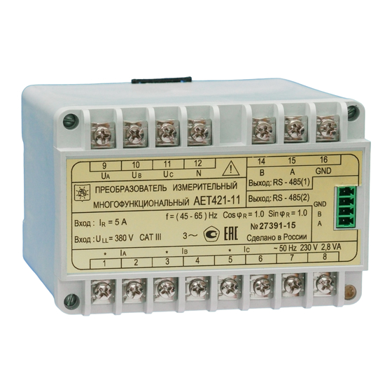
Page 28: Annex A. General Form Of The Transducer
47113964.2.023РЭ Annex А (informative) General Form of the transducer Figure А.1... -
Page 29: Annex B. "Setcomplex 3.1 (En)" Description
47113964.2.023РЭ Annex B (informative) “SetComplex 3.1 (EN)” Description B.1 The «SetComplex 3.1 (EN)» software is intended for the AET100, AET200, AET300, AET400 Multifunction Measuring Transducer configuration. There are two RS-485 independent interfaces «RS-485(1)» and «RS-485(2)». The software permits to install such settings as: 1) COM-port number 2) RS-485 data exchange parameters: - rate of exchange;... - Page 30 47113964.2.023РЭ B.2 Main operation B.2.1 Software installation B.2.1.1 Insert the software CD is enclosed to the transducer. Open the folder : \«Документация и программное обеспечение»\ «Preob AEТ»\. Copy the «Programs» folder to the work disk. B.2.1.2 Connect the «RS-485(2)» transducer interface to USB computer interface by «RS-485 – USB»...
- Page 31 47113964.2.023РЭ Figure B.2 B.2.2.3 Error notification appears in case of incorrect COM-port. Select the correct COM-port and press the «Read» button iteratively. B.2.3 Setting of the data exchange parameters by RS-485. B.2.3.1 Set the requisite RS-485 transducer interfaces parameters at the appropriate areas. - choose the communication protocol from the «Protocol»...
- Page 32 47113964.2.023РЭ Figure B.3 Set the installed transducer address to the « RS-485-1» and «RS-485-2» areas. The default address is «1». B.2.3.2 The «Memory cell size, byte» area defines the address quantity in one register (Address quantity = Register size / Memory cell size). The address quantity is a round up integer number. B.2.3.3 The «Field size «Address of ASDU», «Field size «Information object address», «AS- DU», «Field size «Cause of transmission»...
- Page 33 47113964.2.023РЭ B.2.4 Measurement mode setting B.2.4.1 The transducer measurement mode is selected between three-wire and four-wire con- nection by «3-wire/4-wire» switch. B.2.5 Data register setting B.2.5.1 The «Measured parameteres» area contains the list of the each measurand with relevant register address, register size (byte), resolution factor (k1, k2 or k3). When «3-wire»...
- Page 34 47113964.2.023РЭ Figure B.5 B.2.6.2 The «ExtDev» protocol is intended to incessant transmission (without enquiry message) of the measurement data by «RS-485(2)» interface to the external indication device. External indica- tion device is supplied on separate order. - AED is the seven-segment display indication device. It indicates three selected parameters and set points (30 devices into one transducer maximum).
- Page 35 47113964.2.023РЭ Figure B.6 B.2.6.6 The «Set point < » and «Set point > » columns at the «Measured parameters» table re- flects the transducer configuration to be sent to the AED indication device nominal value. The default reduction set point is 0,1 relating to the nominal value of the measurand. The default growth set point is 1,1 relating to the nominal value of the measurand.
- Page 36 47113964.2.023РЭ Figure B.7 To save a selection, press the «OK» button. The introduced data is displayed at the main program menu. Notification - the information about activities with «Revers» table column isn’t described in this op- eration manual. This table column is reserved. B.2.6.8 The «SetIndikator»...
- Page 37 «Configuration file» area by mouse double-click. Open and load the factory setting file. The fac- tory setting files are contented in the «Programs \ Data» folder and represented as: - cooperative with MODBUS connection protocol: «AET_***_MB.dat» for AETххх transducer without timestamp. «AET_***_MB_RTC.dat» for AETххх transducer with timestamp. - cooperative with IEC 60870-5-101 connection protocol: «AET_***_IEC.dat»...
-
Page 38: Annex C. "Complexmet 3 En" Description
“ComplexMet 3 EN” Description C.1 Introduction The «ComplexMet 3 EN» program is intended for the displaying and saving of the AET transducer output data by RS-485 interface. All information about program is contained at the «About ComplexMet 3 EN» window that is in- voked from the program heading. - Page 39 47113964.2.023РЭ Figure B.1 C.3.3 The working area of the main program menu consists of : -The working area shows the actual values of the measurand: Current; Voltage ; Frequency; Active power; Reactive power; Apparent power; Reactive power (modulus) Note: Depends on transducer type and measurement mode some parameters could be not measured, in this case such parameters are dimmed.
- Page 40 47113964.2.023РЭ «Record time» check-box. The ticked check-box allows to set a run time of the data recording. «Remains» field. Information field displays the remaining data recording time. «Clock synchronization» button (time synchronization). «Delay acquisition» button is intended to activate the delay time procedure, when «IEC» proto- col is applied.
-
Page 41: Annex D. Variants Of Transducer Mounting
47113964.2.023РЭ Annex D (informative) Variants of transducer mounting Figure D.1 Mounting on the Rail Figure D.2 Mounting on the Panel... -
Page 42: Annex E. Diagrams Of Transducer Connections
47113964.2.023РЭ Annex E (informative) Diagrams of transducer connections Note: connection, implemented by dotted line, could be absent. Figure E.1. Four-wire connection with voltage transformers Note: connection, implemented by dotted line, could be absent. Figure E.2. Four-wire connection without voltage transformers... - Page 43 47113964.2.023РЭ Note: connection, implemented by dotted line, could be absent. Figure E.3. Three-wire connection with voltage transformers Note: connection, implemented by dotted line, could be absent. Figure E.4. Three-wire connection without voltage transformers...
- Page 44 47113964.2.023РЭ Note: connection, implemented by dotted line, could be absent. Figure E.5. Three-wire connection with two voltage transformers and two current transformers Note: connection, implemented by dotted line, could be absent. Figure E.6. Three-wire connection with two voltage transformers and two current transfor- mers(phase B current measurement)
- Page 45 47113964.2.023РЭ 1, R 2 – Resistor С2-33-0,25 W –120 Ω ± 5% Wire section is no less than 0,2 mm Figure E.7. RS-485 interface connection...
-
Page 46: Annex F. The Form Of Calibration Protocol
47113964.2.023РЭ Annex F The form of the calibration protocol of the transducer Protocol of calibration Transducer ____________ №__________, Inhering _______________________________ Type Serial number The name of firm is verified by ______________________________________ _______________ . The name of firm making verification Year, month, date F.1 Calibration condition Ambient Air Temperature ______________________________ °С... - Page 47 47113964.2.023РЭ Line-to-neutral Voltage Tests (4-Wire F.5.2 Transducer Transducer Transducer Transducer under under test read- under test under test test reading reading reading В1 С1 Value, Out- Value, Out- Value, Out- Value, V code code code =____________ k1 = __________ L-N nom Conclusion: _____________________________________________________________________________ 5.3 Current Tests (4-Wire) Transducer un-...
- Page 48 47113964.2.023РЭ Zero-sequence Current Tests F.5.5 (4-Wire) Check point Transducer under test reading Intrinsic error γ, % А Iо Iо Output code Value, А =____________ k1 = __________ Conclusion: _____________________________________________________________________________ 5.6 Active Power Tests, per phase (4-Wire) Check point Transducer un- Transducer un- Transducer under der test reading...
- Page 49 47113964.2.023РЭ 5.8 Reactive Power Tests, per phase Q sinφ (4-Wire) ph· Check point Transducer under Transducer under Transducer under test reading test reading test reading А1 Voltage Current, Phase Power Output Value, Output Value, var Output Value, line-to- angle, code code code А0...
- Page 50 47113964.2.023РЭ 5.10 Apparent Power Test, per phase (4-Wire) Check point Transducer Transducer un- Transducer under test read- der test reading under test read- А1 Voltage Current, Phase Power Output Value, Out- Value, Out- Value, line-to- angle, code V⋅A V⋅A V⋅A А0 line, degree...
- Page 51 47113964.2.023РЭ F.5.12 Apparent Power of the System Tests (4-Wire) Check point Transducer under test reading Voltage Current, Phase angle, cos φ Standard Output Value, V⋅A line-to- А reading code degree line, V Sо, V⋅A =____________ k2 = __________ Conclusion: _____________________________________________________________________________ F.5.13 Frequency Tests Standard reaing, Tested Transducer reading...
- Page 52 47113964.2.023РЭ Line-to-neutral Voltage Tests (4-Wire F.5.15 Transducer un- Transducer un- Transducer un- Transducer un- der test reading der test reading der test reading der test reading В1 С1 Output Value, Output Value, Output Value, Output Value, code code code code =____________ k1 = __________ Conclusion: _____________________________________________________________________________...
- Page 53 47113964.2.023РЭ of the System F.5.18 Apparent Power Tests (3-Wire) Check point Transducer under test reading Voltage Current, Phase angle, cos φ Standard Output Value, V⋅A line-to- А reading code degree line, V Sо, V⋅A =____________ k2 = __________ Conclusion: _____________________________________________________________________________ 6 Common conclusion _________________________________________________________ Certificate of calibration (number) is granted, or the reason of unsuitability The chief of a gauge service...
Need help?
Do you have a question about the AET111 and is the answer not in the manual?
Questions and answers