Advertisement
Available languages
Available languages
Quick Links
P.O. Box 342, Delavan, WI 53115
Phone: 1-800-365-6832
Fax: 1-800-526-3757
E-Mail: info@flotecwater.com
Web Site: http://www.flotecwater.com
Installation/Operation/Parts
For further operating, installation,
or maintenance assistance:
Call 1-800-365-6832
English
Pages 2-14
. . . . . . . . . . . . . .
©2006
®
FPPC-5850
Installation/Fonctionnement/Pièces
Pour plus de renseignements
concernant l'utilisation,
l'installation ou l'entretien,
Composer le 1 (800) 365-6832
Français
. . . . . . . . . . .
OWNER'S MANUAL
In-Ground Pool Cleaner
NOTICE D'UTILISATION
Nettoyeur automatique
de piscine creusée
MANUAL DEL USUARIO
Limpiador de
piscinas excavadas
Instalación/Operación/Piezas
Para mayor información sobre el
funcionamiento, instalación o
mantenimiento de la bomba:
Llame al 1-800-365-6832
Español
Pages 15-27
Paginas 28-40
. . . . . . . . . . .
1000001161 (Rev. 2/8/06)
Advertisement

Related Manuals for Flotec FPPC-5850


Summary of Contents for Flotec FPPC-5850
- Page 1 Nettoyeur automatique Fax: 1-800-526-3757 E-Mail: info@flotecwater.com de piscine creusée Web Site: http://www.flotecwater.com MANUAL DEL USUARIO Limpiador de piscinas excavadas FPPC-5850 Installation/Fonctionnement/Pièces Instalación/Operación/Piezas Installation/Operation/Parts Pour plus de renseignements Para mayor información sobre el For further operating, installation, concernant l’utilisation, funcionamiento, instalación o or maintenance assistance: l’installation ou l’entretien,...
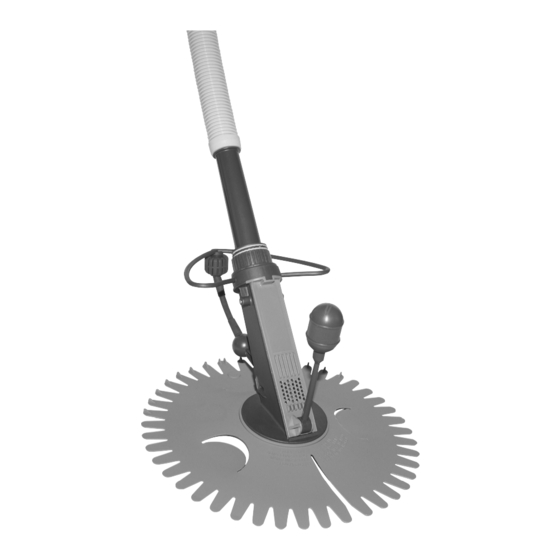
- Page 2 Pipe and Nut Assembly to perform routine mainte- lessen the load on your pump and reduce electricity and nance on the cleaner. pump repair bills. Your cleaner is assembled! 1-800-365-6832 For parts or assistance, call Flotec Customer Service at...
- Page 3 If within ninety (90) days from original consumer purchase any Drill Pump, tive product to the Retail outlet or to FLOTEC as soon as possible after the dis- Pitcher Pump, or In-Line Water Filter Cartridge shall prove to be defective, it covery of any alleged defect.
- Page 4 Figure 1N - Short Extension Figure 1K - Hose Weight. tor with two male ends. Hose. Not illustrated - 6” M/M Hose Section Figure 1D - Regulator Valve Cover. Figure 2B Figure 2A 1-800-365-6832 For parts or assistance, call Flotec Customer Service at...
- Page 5 For best results and to retain your warranty, use only gen- uine Flotec hoses. Join the Flotec hose sections one to another by fitting the male end to the female end of the added section (see Figure 3). Make sure the connections are snug. The num- ber of lengths that you will need depends on the size of your pool.
- Page 6 This will help prevent possible injury from the pool pump’s suction should the hose become detached from the regulator valve. Yellow Band Figure 7 Side Opening Figure 8 Figure 9 Figure 10 1-800-365-6832 For parts or assistance, call Flotec Customer Service at...
- Page 7 This arrangement will provide some skimming action through the skimmer, and will regulate the flow through the cleaner. Skimmer Port 4018 0701 Figure 14 Figure 12 1-800-365-6832 For parts or assistance, call Flotec Customer Service at...
- Page 8 (See NOTE, above). • Now take a look at the regulator valve and determine whether the base of the sliding barrel has moved into the area of the yellow band. 1-800-365-6832 For parts or assistance, call Flotec Customer Service at...
- Page 9 Simply STOP THE PUMP unscrew the nut at the base of the connecting tube, and lift the lid covering the chamber (see Figure 18). 1-800-365-6832 For parts or assistance, call Flotec Customer Service at...
- Page 10 Remove all debris and rinse the (Pages 12, 13 and 14). chamber before replacing the lid and reattaching • The Flotec hose is especially designed for use with the nut and connecting tube. your Flotec cleaner. For proper performance and reten- •...
- Page 11 • Is there too much or too little suction? Refer to the suggestions under (1) above. 1-800-365-6832 For parts or assistance, call Flotec Customer Service at...
- Page 12 Valve by sliding out the retaining Valve and Lid/Float from the steel ends. pin. Figure 20D - Flapper Valve, Part No. 41101-0102. Figure 20C - Lid and Float, Part No. 41101-0128C. 1-800-365-6832 For parts or assistance, call Flotec Customer Service at...
- Page 13 A spoon can help, if needed. Figure 22D - Foot-Pad, Figure 23A - Ladder Deflector, clips Figure 23B - Clip Ladder Deflector Part No. 41101-0101C. to Pipe and Nut Assembly. to Bumper. 1-800-365-6832 For parts or assistance, call Flotec Customer Service at...
- Page 14 Part No. 41201-0238. Port Figure 24H - Ladder Deflector, Figure 24I - Vac Port Fitting, Figure 24J - Short Extension Hose, Part No. 41101-0116. Part No. 41100-0122. Part No. GW9530. 1-800-365-6832 For parts or assistance, call Flotec Customer Service at...
- Page 15 également la charge Votre nettoyeur automatique est assemblé! imposée sur la pompe, vos factures d’électricité seront moins 1 (800) 365-6832 Pour les services des pièces ou d'assistance, appeler le service à la clientèle Flotec en composant le...
- Page 16 FLOTEC • P.O. Box 342 • Delavan, WI U.S.A. 53115 Téléphone: 1-800-365-6832 • Télécopieur: 1-800-526-3757 Courrier électronique: info@flotecwater.com • Site Web: http://www.flotecwater.com 1 (800) 365-6832 Pour les services des pièces ou d'assistance, appeler le service à la clientèle Flotec en composant le...
- Page 17 Figure 1D – Couvercle pro- Pas illustré – Tuyau souple de 6 po à tecteur du régulateur embouts mâle-mâle. d’aspiration. Figure 2B Figure 2A 1 (800) 365-6832 Pour les services des pièces ou d'assistance, appeler le service à la clientèle Flotec en composant le...
- Page 18 Si le tuyau souple flotte trop, posez des mass- es d’alourdissement, comme il est illustré à la Figure 6. 1 (800) 365-6832 Pour les services des pièces ou d'assistance, appeler le service à la clientèle Flotec en composant le...
- Page 19 à se détacher du régulateur d’aspiration automatique. Bande jaune Figure 7 Ouverture latérale Figure 8 Figure 9 Figure 10 1 (800) 365-6832 Pour les services des pièces ou d'assistance, appeler le service à la clientèle Flotec en composant le...
- Page 20 Orifice Écumoire Skimmer Port d’aspiration 4018 0701 Figure 14 Figure 12 1 (800) 365-6832 Pour les services des pièces ou d'assistance, appeler le service à la clientèle Flotec en composant le...
- Page 21 Maintenant, regardez le régulateur d’aspiration et déter- minez si la base du manchon coulissant s’est déplacée dans la partie de la bande jaune. 1 (800) 365-6832 Pour les services des pièces ou d'assistance, appeler le service à la clientèle Flotec en composant le...
- Page 22 POMPE, dévissez l’écrou qui se trouve à la base du tube de raccordement, puis levez le couvercle recouvrant la cham- bre (reportez-vous à la Figure 18). 1 (800) 365-6832 Pour les services des pièces ou d'assistance, appeler le service à la clientèle Flotec en composant le...
- Page 23 écrou, ouvrez le couvercle du clapet à battant de votre Figure 18 nettoyeur automatique et assurez-vous que le battant du clapet est adéquatement retenu sur l’axe en acier. 1 (800) 365-6832 Pour les services des pièces ou d'assistance, appeler le service à la clientèle Flotec en composant le...
- Page 24 – n’utilisez que des longueurs de tuyau souple d’origine Flotec. 1 (800) 365-6832 Pour les services des pièces ou d'assistance, appeler le service à la clientèle Flotec en composant le...
- Page 25 Figure 20D – Clapet à battant, nº de pièce 41101-0102. Figure 20C – Couvercle et flotteur, nº de pièce 41101-0128C. 1 (800) 365-6832 Pour les services des pièces ou d'assistance, appeler le service à la clientèle Flotec en composant le...
- Page 26 Figure 23A – Déflecteur d’échelle; Figure 23B – Agrafez le déflecteur 41101-0101C. s’agrafe sur l’ensemble tuyau et d’échelle sur le butoir. écrou. 1 (800) 365-6832 Pour les services des pièces ou d'assistance, appeler le service à la clientèle Flotec en composant le...
- Page 27 Figure 24J - Petite longueur nº de pièce 41101-0116. de tuyau souple, nº de pièce d’orifice de nettoyage à l’aspirateur 41100-0122. (vac port). 1 (800) 365-6832 Pour les services des pièces ou d'assistance, appeler le service à la clientèle Flotec en composant le...
- Page 28 Esto también dis- minuirá la carga aplicada sobre la bomba, reducirá la electrici- dad y las facturas de reparación de la bomba. 1 800 365-6832 Para refacciones o asistencia, llame a Flotec Servicios al Cliente al:...
- Page 29 FLOTEC, sujeto a los términos y a las carse en su caso. Esta garantía le concede derechos legales específicos. Usted condiciones indicadas a continuación.
- Page 30 Figura 1D - Cubierta de la No ilustrada - Sección de anguera de 6” M/M. válvula reguladora. Figura 2B Figura 2A 1 800 365-6832 Para refacciones o asistencia, llame a Flotec Servicios al Cliente al:...
- Page 31 Pruebe el extremo hembra. limpiador primero sin ninguna pesa para manguera. Si la manguera flota demasiado, agregue una pesa según se ilustra en la Figura 6. 1 800 365-6832 Para refacciones o asistencia, llame a Flotec Servicios al Cliente al:...
- Page 32 Banda amarilla Figura 7 Abertura lateral Figura 8 Figura 10 Figura 9 1 800 365-6832 Para refacciones o asistencia, llame a Flotec Servicios al Cliente al:...
- Page 33 Figura 12. espumadera y regular el flujo a través del limpiador. Puerto de Espumadera Skimmer aspiración Port 4018 0701 Figura 14 Figura 12 1 800 365-6832 Para refacciones o asistencia, llame a Flotec Servicios al Cliente al:...
- Page 34 (Consulte la NOTA arriba). • Ahora mire la válvula reguladora y determine si la base del cilindro corredizo se ha movido hacia el área de la banda amarilla. 1 800 365-6832 Para refacciones o asistencia, llame a Flotec Servicios al Cliente al:...
- Page 35 Simplemente DETENGA LA BOMBA, destornille la tuerca en la base del tubo conector, y levante la tapa que cubre la cámara (consulte la Figura 18). 1 800 365-6832 Para refacciones o asistencia, llame a Flotec Servicios al Cliente al:...
- Page 36 • DETENGA LA BOMBA, abra la tapa del Limpiador y asegúrese de que la válvula de aleta esté debidamente enganchada al pasador de acero. Figura 18 1 800 365-6832 Para refacciones o asistencia, llame a Flotec Servicios al Cliente al:...
- Page 37 Nunca use una manguera de aspiración manual ni mangueras de otros fabricantes – use solamente mangueras genuinas Flotec. 1 800 365-6832 Para refacciones o asistencia, llame a Flotec Servicios al Cliente al:...
- Page 38 Flotador del pasador de acero. Figura 20D – Válvula de aleta, Repuesto No. 411-0102. Figura 20C – Tapa y Flotador – Repuesto No. 41101-0128C. 1 800 365-6832 Para refacciones o asistencia, llame a Flotec Servicios al Cliente al:...
- Page 39 Figura 23A – Deflector de escala, se Figura 23B – Enganche el Deflector Repuesto No. 41101-0101C. engancha en la Unidad de Tubo y de escala en el Tope. Tuerca. 1 800 365-6832 Para refacciones o asistencia, llame a Flotec Servicios al Cliente al:...
- Page 40 Figura 24H – Deflector de escala, Figura 24I - Accesorio para el Figura 24J - Manguera corta de Repuesto No. 41101-0116. alargue. orificio de aspiración, Repuesto No. GW9530. 1 800 365-6832 Para refacciones o asistencia, llame a Flotec Servicios al Cliente al:...
Need help?
Do you have a question about the FPPC-5850 and is the answer not in the manual?
Questions and answers