
Summary of Contents for ABLE BA688CF-P
- Page 1 Installation & Maintenance Instructions BA688CF-P Supplied by .com Call us on +44 (0)118 916 9420 | Email info@247able.com...
- Page 2 Installation & Maintenance Instructions BA688CF-P PROFIBUS PA panel mounting fieldbus display Reading Office Aberdeen Office Cutbush Park, Danehill, Lower Earley, Unit 6 Airside Business Park, Kirkhill Industrial Estate, Internet: www.able.co.uk Reading, Berkshire. RG6 4UT. UK. Dyce, Aberdeen. AB21 0GT. UK.
- Page 3 BA688CF-P PROFIBUS PA Panel mounting Fieldbus Display issue 3 Issue: 3 December 2011...
-
Page 4: Table Of Contents
Last Input 5.3.7 Keys 5.3.8 Code 5.3.9 Unit Info 5.3.10 Defaults 5.3.10.1 Display Defaults 5.3.10.2 Interface Board defaults. 5.3.11 Instrument address 5.4 Quick Access Menu The BA688CF-P PROFIBUS display is CE marked to show compliance with the European EMC Directive 2004/108/EC... -
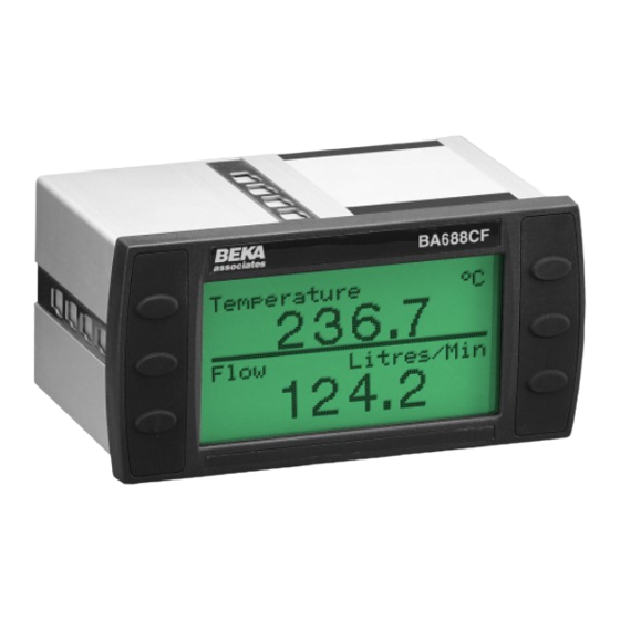
Page 5: Description
Version 3.0 firmware is shown as operator acknowledgements, thus enabling the SW480F-02-300. BA688CF-P PROFIBUS display to function as a simple operator interface. If larger industrial push For BA688CF-P PROFIBUS displays employing buttons required... -
Page 6: Operation
How much of the BA688CF-P PROFIBUS display configuration can be performed via the fieldbus depends upon the system host. Parameters that can not be configured via the fieldbus can be set using the configuration menu shown in Fig 6 and the four front panel push buttons. -
Page 7: System Design
3. SYSTEM DESIGN 3.2 Alarm outputs Each alarm output is a galvanically isolated single The BA688CF-P may be connected to any pole solid state switch output as shown in Fig 3. PROFIBUS PA segment as shown in Fig 2 providing it can provide the additional 25mA required to operate the BA688CF-P PROFIBUS display. -
Page 8: Installation
4.2 Installation Procedure a. Insert the BA688CF-P into the instrument 4.1 Location The BA688CF-P PROFIBUS display is housed in a panel cut-out from the front of the panel. robust aluminium enclosure with a toughened glass window mounted in a Noryl bezel. The front b. -
Page 9: Emc
4.3 EMC The BA688CF-P complies with the requirements of the European EMC Directive 2004/108/EC. specified immunity all wiring should be in screened twisted pairs with the screens connected to the plant’s potential equalising network. -
Page 10: Display & Alarm Configuration
GSD files onto the system host and menu. If the BA688CF-P is not protected by an defining up to eight fieldbus variables that are to be access code the main menu will be displayed. If... -
Page 11: Configurable Functions
PROFIBUS PA address. Two variables + horizontal bargraphs 5.3.1 Screens (Display format) The BA688CF-P can display up to eight fieldbus variables that are identified as IN_1 to IN_8. The fieldbus variable that each one represents is determined by the BA688CF-P configuration at the... -
Page 12: Input Settings
Six options are available: 5.3.5 Alarms Auto: Max resolution with selected Alarm menus are only included when the BA688CF-P display format. is fitted with optional alarm outputs. Outputs are 4 DP 4 digits on right of decimal point... -
Page 13: Alarm Activation
BA688CF-P front panel push buttons. The table use the ▼ or ▲ button to toggle the setting. Enter below shows the function of the BA688CF-P front the selection by pressing the E button. panel and the external push buttons for each of the... -
Page 14: Unit Info
If an access code other than the default code 0000 has already been entered, the BA688CF-P PROFIBUS display will request that the access code be entered. 5.3.10 Defaults This function enables the display and interface board factory defaults to be restored. -
Page 17: Maintenance
BA688CF-P fails function during commissioning the following procedure should be followed: If a BA688CF-P fails after it has been functioning correctly, the table shown in section 6.1 may help to identify the cause of the failure. Symptom Cause Check: No Display... -
Page 18: Accessories
7. ACCESSORIES 7.1 Tag number The BA688CF-P can be supplied with a thermally printed tag number on the rear panel. This tag number is not visible from the front of the instrument after installation. 7.2 PROFIBUS Interface Guides The BEKA PROFIBUS Interface Guide, which may... -
Page 19: Index
9. INDEX Subject Section Subject Section Address 5.3.11 Number Format 5.3.2 Alarms 5.3.5 Activation 5.3.5.2 PROFIBUS PA 1; 1.2 Output 5.3.5.3 Summary 5.3.5.1 Quick access menu 5.3.6.2; 5.4 Backlight 5.3.6.1 Servicing Bargraph Limits 5.3.2 Screens (display format) 5.3.1 Status text 5.3.6.4 Configuration menu Fig 6...
Need help?
Do you have a question about the BA688CF-P and is the answer not in the manual?
Questions and answers