Advertisement
control – motion –
• Impulse input (A, /A, B, /B, Z, /Z, TTL level or HTL level)
• Potential separation by high speed opto-couplers
• 6 output channels, each (A, /A, B, /B, Z, /Z)
GV150: all outputs TTL / RS422
GV151 outputs individually programmable to either TTL or HTL level
• Frequency range 0 - 400 kHz
• Front LED's for indication of input pulses A, B and Z
• Elimination of noise and cross talking on transmission lines
• Closed aluminum cassette for mounting in 19"racks or assembly on
DIN mounting rails
GV15002B_e.DOC / Mrz-08
interface
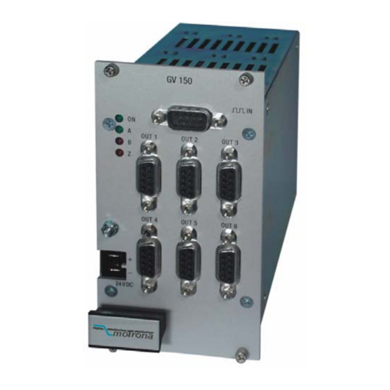
GV150 / GV151
Impulse Amplifier and Splitter
for Encoder Signals
Operating Instructions
motrona GmbH
Zwischen den Wegen 32
78239 Rielasingen - Germany
Tel. +49 (0)7731-9332-0
Fax +49 (0)7731-9332-30
info@motrona.com
www.motrona.com
Page 1 / 8
Advertisement
Table of Contents

Related Manuals for Motrona GV150

Summary of Contents for Motrona GV150
- Page 1 • Potential separation by high speed opto-couplers • 6 output channels, each (A, /A, B, /B, Z, /Z) GV150: all outputs TTL / RS422 GV151 outputs individually programmable to either TTL or HTL level • Frequency range 0 - 400 kHz •...
- Page 2 • Regarding installation, wiring, environmental conditions, screening of cables and earthing, you must follow the general standards of industrial automation industry • - Errors and omissions excepted – Version: Description: GV15002B/hk_03/2008 First motrona edition with A5 brochure format GV15002B_e.DOC / Mrz-08 Page 2 / 8...
- Page 3 Table of Contents 1. Application and Construction................4 2. Connections, Switch Settings................. 5 3. Block Diagram....................6 4. Input Pin Assignment..................7 5. Output pin assignment..................7 6. Technical Data ....................8 GV15002B_e.DOC / Mrz-08 Page 3 / 8...
- Page 4 30 mA per line. The units can be used for encoder pulse transmission and for data transmission applications as well. As a standard, GV150 and GV151 provide TTL (RS422) inputs (A, /A, B, /B, Z, /Z) With Option HTLIN1, the input is set to HTL level (12...30V), and only the signals A, B and Z necessary (no inverted signals).
- Page 5 2. Connections, Switch Settings The unit is supplied by a power connector on the front side. The power supply range is 18 - 30 VDC. For operation without potential separation, positions 3 and 4 of the internal DIL switch S1 can be set to "ON". This will connect the input GND to the output GND and to the Minus potential of the power supply Pin 4 of the input connector provides an auxiliary voltage output, when the DIL-switch positions 1 and 2 are set to "ON".
- Page 6 3. Block Diagram GV151 (GV150-1) +24V OPTO OUT 1 OUT 2 GV150 GV150 GV150-1 GV151 OUT 3 OUT 4 OUT 5 OUT 6 Power 24 VDC GV15002B_e.DOC / Mrz-08 Page 6 / 8...
- Page 7 4. Input Pin Assignment (Sub-D-9 male on the unit) * See DIL switch S1 +24V GND +24V GND +5,5V GND Option HTLIN1 Option HTLIN2 Standard TTL 5. Output pin assignment (Sub-D-9 female on the unit) 1 2 3 4 5 6 7 8 1 2 3 4 (GV151) B +5V Z...
- Page 8 : TTL input (A, /A, B, /B, Z, /Z), GV150/ GV 151 / HTLIN1 : HTL input A, B, Z GV150/ GV 151 / HTLIN2 : HTL input (A, /A, B, /B, Z, /Z) Option SM 150 : Backplane prepared for DIN rail mounting.
Need help?
Do you have a question about the GV150 and is the answer not in the manual?
Questions and answers