Table of Contents
Advertisement
This is the safety alert symbol. It is used to alert you to potential personal injury hazards.
Obey all safety messages that follow this symbol to avoid possible injury or death.
English
Master Language
STi Pulse Timer Range
Installation and Operation Manual
Installation, Operation, and Service Information
13IAF023 (07/14)
Revision 3
Advertisement
Table of Contents

Summary of Contents for Donaldson Torit STi ODC-TC
- Page 1 STi Pulse Timer Range Installation and Operation Manual Installation, Operation, and Service Information This is the safety alert symbol. It is used to alert you to potential personal injury hazards. Obey all safety messages that follow this symbol to avoid possible injury or death. 13IAF023 (07/14) English Master Language...
- Page 2 Donaldson Company, Inc. PLEASE READ THIS DOCUMENT CAREFULLY PRIOR TO INSTALLATION AND/OR START UP. IT CONTAINS SPECIFIC PRECAUTIONARY STATEMENTS RELATIVE TO WORKER AND EQUIPMENT SAFETY. THIS DOCUMENT SHOULD BE READ IN CONJUNCTION WITH THE INSTALLATION, OPERATION AND MAINTENANCE MANUAL OF THE DUST COLLECTOR UNIT WHOSE REVERSE JET PULSE CLEANING SYSTEM IT IS TO CONTROL. WARNING, used with the safety alert symbol, indicates a hazardous situation which, if not avoided, could result in personal injury and extensive damage.
-
Page 3: Table Of Contents
STi Timer Range Contents 1 Timer Description ..................................4 2 Installation Guide ..................................8 Mechanical Installation ..............................8 Electrical Installation ..............................11 2.2.1 Connections on the master card ........................... 11 2.2.2 Connections on the extension card(s) ......................... 17 Pneumatic Installation ..............................24 2.3.1 Check connection of solenoid valves to diaphragm valves ................ -
Page 4: Timer Description
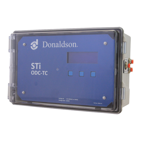
Donaldson Company, Inc. TIMER DESCRIPTION The timer is available in two standard configurations. In The Solid state pulse Timer intelligent (STi) is the newest the DC configuration these timers drive 24VDC valves addition to the Donaldson range of timers. This timer where the input to the timer can be between 110-240 gives a versatile range of options for controlling the VAC or 24VDC. - Page 5 STi Timer Range STi basic version STi ODC version STi ODC-TC version Basic Functional Description The basic version The ODC version pulses the This version operates automatically pulses the valves when it detects that similar to an ODC version valves at regular intervals...
- Page 6 Donaldson Company, Inc. STi basic version STi ODC version STi ODC-TC version Counter for recording total as well as number of pulses generated in a session Code protection for settings update INPUTS AVAILABLE Power supply requirements 24VDC or 110-240VAC 24VDC or 110-240VAC...
- Page 7 STi Timer Range STi basic version master cards STi ODC and ODC-TC versions master cards Figure 1: STi master cards (a) basic version and (b) ODC / ODC-TC version. Note the legacy AC version has different circuitry.
-
Page 8: Installation Guide
Donaldson Company, Inc. By default, the order in which the timer pulses the valves NOTE is consecutive (standard pulse sequence) however it is possible to define an arbitrary pulse sequence during Timers ordered as spare parts are not supplied with commissioning. - Page 9 STi Timer Range Siloair Unit Series VS Dalamatic Cased Unit Series DLMC Downflo Oval Unit Series DFO Dalamatic Insertable Venting Unit Series DLMV Powercore Series CPV Figure 3 : Location of STi timer master and extension card enclosure(s) on different Donaldson dust collectors...
- Page 10 Donaldson Company, Inc. Powercore Series CPC Powercore Series VH Figure 3: Location of STi timer master and extension card enclosure(s) on different Donaldson dust collectors Depending on the dust collector unit that the timer has been configured for, it may be supplied with or without solenoid valves fitted on the enclosure.
-
Page 11: Electrical Installation
STi Timer Range ELECTRICAL INSTALLATION J109 Relay contacts for Alarm on Interrupt/Sensor 1 state (not available on basic version) 2.2.1 Connections on the master card J111 Relay contacts for Alarm on Interrupt/Sensor 2 Step 1 Access the input/output terminals on the master state (not available on basic version) card J113 Relay contacts for System Health Alarm... - Page 12 Donaldson Company, Inc. If two or more enclosures for the extension cards are NOTE supplied, a 1m industrial grade CAT5 cable is provided to link the different extension cards, in addition to the The STi timer monitors the current drawn by the coil standard 5m cable for linking the first (closest) extension of each solenoid valve when it is activated and uses card to the master card.
- Page 13 STi Timer Range STi Master Card E A B 2A G CARD VERSION 3.2 STi Extension Card 0v 24v 0v 24v 8 7 6 5 4 3 2 1 STi Extension Card 0v 24v 0v 24v 8 7 6 5 4 3 2 1 STi Extension Card 0v 24v 0v 24v...
- Page 14 Donaldson Company, Inc. Optional Step 4 Activate Offline Cleaning Finally, if power to the timer is lost, the timer recognises that the pulse cleaning system has been de-energised Depending on the nature of the product being collected and filters are not being cleaned. by the dust collector, this product might adhere to the filter elements when the fan is running.
- Page 15 STi Timer Range If the pulsing of the valves has been paused either Optional Step 7 Activate Remote Interrupt Function manually at the timer or using the remote interrupt It is possible to remote interrupt (temporarily pause) the feature, the timer triggers this relay. pulsing of the solenoid valves by passing a digital signal The STi timer and the valves need to be serviced at to the input terminals 1-D or 2-D and G of J1 or J2.
- Page 16 Donaldson Company, Inc. Table 4: External Sensor Monitor Relays Trigger Map NOTE (OFF = Sensor within range) The 4-20 mA current loop has been designed to Alarm type Relay On Relay Off interface with an external device with an input Sensor readout At/beyond Before threshold...
-
Page 17: Connections On The Extension Card(S)
STi Timer Range the CAT5 cable to the 0V and +ve contacts of the RS 485 2.2.2 Connections on the extension card(s) power bus on the extension card. Each STi extension card contains 2 RS 485 bus contacts, If the extension card is independently powered, it might 10 solenoid active contacts, 2 solenoid common contacts be necessary to suitably insulate the connection leads and 8 DIP switches as shown in Figure 6. - Page 18 Donaldson Company, Inc. Step 2 Configure DIP switches There are a set of 8 DIP switches on the bottom left corner of each extension card. These DIP switches control how the extension card sends and receives information to and from the STi timer master card, allowing the master to maintain effective control over the solenoid valves connected to extension card.
- Page 19 STi Timer Range EXTENSION CARD 1 EXTENSION CARD 2 EXTENSION CARD 3 EXTENSION CARD 4 EXTENSION CARD 5 Figure 8: DIP switch configuration for Example 1 Example 2 – DIP switch settings for extension cards connected to a master with no valves fitted. Valves pulse sequentially.
- Page 20 Donaldson Company, Inc. EXTENSION CARD 1 EXTENSION CARD 2 EXTENSION CARD 3 Figure 10: DIP switch configuration for Example 3 Example 4 – DIP switch settings for extension cards connected to a master with no valves fitted. Valves connected to extension cards 1 to 4 pulse together.
- Page 21 STi Timer Range EXTENSION CARD 1 EXTENSION CARD 2 EXTENSION CARD 3 EXTENSION CARD 4 EXTENSION CARD 5 Figure 12: DIP switch configuration for Example 5 Example 6 – DIP switch settings for extension cards connected to a master with no valves fitted. Valves connected to extension cards 1 to 3 pulse together, and valves on extension cards 4 to 6 pulse together.
- Page 22 Donaldson Company, Inc. COMPRESSED AIR MANIFOLDS ON DUST COLLECTOR EACH FITTED WITH 8 DIAPHRAGM VALVES BANK 1 BANK 2 BANK 3 MASTER EXT 1 EXT 2 PULSE SEQUENCING ALGORITHM SET IN ARBITRARY MODE WITH NO. OF VALVES SET AT 24. BANK 1 BANK 2 BANK 3...
- Page 23 STi Timer Range COMPRESSED AIR MANIFOLDS ON DUST COLLECTOR EACH FITTED WITH 8 DIAPHRAGM VALVES BANK 1 BANK 2 BANK 3 MASTER EXT 1 EXT 2 EXT 3 EXT 4 EXT 5 EXT 6 EXT 7 EXT 8 PULSE SEQUENCING ALGORITHM SET IN ARBITRARY MODE WITH NO. OF VALVES SET AT 24. BANK 1 BANK 2 BANK 3...
-
Page 24: Pneumatic Installation
Donaldson Company, Inc. Step 3 Check connection of solenoid valves to the card Step 1 Check the hose connections from the bulkhead terminals fittings on the master enclosure to the pressure sensor on the master card. The STi extension enclosure is normally supplied with solenoid valves fitted to it. - Page 25 STi Timer Range The bulk head and push in fittings as well as the tube cleaner itself is rated to withstand a maximum pressure of 7 bar (approximately 100 psi). Connecting a compressed air supply at a higher pressure than this will cause irreversible damage to the tube cleaner and the entire timer in general.
-
Page 26: Operation And Site Reprogramming
Donaldson Company, Inc. OPERATION AND SITE Once inside the programming mode, the user can reprogram the different variables governing the pulse REPROGRAMMING timing algorithms. Table 6 and 7 show the factory set values for the different variables. The STi Timer generally comes pre-programmed from Donaldson customised with optimal pulse timing settings If the pulse cleaning system is to be interlinked with for the Donaldson dust collector that it is intended to... - Page 27 STi Timer Range POWER ON TIMER INITIALISATION EXTENSION DETECTION CONFIGURATION DETECTION INITIALISATION AUTOMATIC MODE SET UP (see Section 4.1) AUTOMATIC STATE* RUN SCREENS PULSING STATE (see Section 4.2) HALTED STATE DONALDSON CARE TIMING CONFIGURATION EMAIL/PHONE NUMBERS REVIEW SETTINGS TIMER SETTINGS (see Section 4.4) PRODUCT ODC SETTINGS*...
- Page 28 Donaldson Company, Inc. Table 6: Pulse Timing Configuration for different Donaldson dust collections Dust Collector Model No. of valves being Pulse sequencing Pulse duration, refer Interval between controlled, refer algorithm, refer Figure 39 pulsing during normal Figure 35 Figure 36 pulsing, refer Figure 40 Dalamatic units DU 7, DU 10,...
- Page 29 STi Timer Range Dust Collector Model No. of valves being Pulse sequencing Pulse duration, refer Interval between controlled, refer algorithm, refer Figure 39 pulsing during normal Figure 35 Figure 36 pulsing, refer Figure 40 Powercore units CPV 1 and Standard 100 ms 10 sec CPV 3...
-
Page 30: Programming The Timer
Donaldson Company, Inc. Table 7: Recommended On Demand Cleaning settings for different dust collector models Collector Type Dust Collector ODC Low Set ODC High Point, ODC High-high ODC Alarm Set Range Point, refer F Set Point, Point, refer Figure 52 igure 53 refer refer Figure 55... -
Page 31: Timer Run Screens
STi Timer Range Figure 22: Configuration confirmation screen in (a) sequential mode, and (b) parallel mode NOTE If a valid configuration is detected, the configuration confirmation screen is displayed for 15 sec, or until a push button is pressed. If an invalid configuration is Figure 21: Detection result screen detected, the timer does not proceed beyond For a configuration to be detected as valid, no two... - Page 32 Donaldson Company, Inc. If an interrupt signal on either of input terminal J1 or J2, NOTE the timer transitions through to Halted State and displays The Automatic State is not available in the basic an interrupt notification INT on the screen. version.
-
Page 33: Temporarily Stop Filter Media Cleaning
STi Timer Range In Pulsing State, the Run screens display the following information: • The timer is operating in the pulsing (PULSE) mode • The valve number that is going to be pulsed next. • The time duration in seconds after which the valve is going to be pulsed Figure 25: (a) Resting, and (b) Active run screens in NOTE... -
Page 34: Review Settings
Donaldson Company, Inc. The Timing Settings Quick Summary screen identifies the REVIEW SETTINGS following information: Timer Configuration screen • The number of valves that are being controlled by the timer. • The order in which these valves are being pulsed, whether one after another starting from valve 1 (STD) or in a user-defined arbitrary order (ARB). -
Page 35: View Service Information
STi Timer Range Auto Pulse Settings Display screen VIEW SERVICE INFORMATION (not shown in basic version) Service Information screen Figure 29: Auto Pulse Settings Display screen Figure 31: Service Information screen The Service Information screen identifies the number of The Auto Pulse Settings Display screen shows the maximum interval between two pulses generated by hours and the number of pulses remaining till the timer is due for a service. -
Page 36: Access Timer Settings
Donaldson Company, Inc. Customers outside Australia or New Zealand should send an email to the Australian email address. A support request should identify the card serial number, the The STi timer is supplied preconfigured to suit the firmware version the card is running and the details dust collector whose cleaning system it is intended to listed on the quality control sticker. - Page 37 STi Timer Range Pressing EXIT returns the timer to the resting run Pressing CHANGE toggles the selection from YES to NO screens. Pressing SELECT brings up the Pulse and vice versa. Pressing SET saves the selection to Sequencing Algorithm Selection screen. Pressing the timer.
- Page 38 Donaldson Company, Inc. Pressing UP or DOWN increments or decrements the Offline Cleaning Activation screen pulse duration. Pressing SET saves the value to the timer and the timer brings up the Interval between pulses in Normal mode selection screen. Interval between pulses in Normal mode selection screen Figure 43: Offline Cleaning Activation screen Pressing CHANGE toggles the selection from Activated...
-
Page 39: Input Handling & Alarms Set Up (Not Shown In Basic Version)
STi Timer Range Pressing A/D toggles the signal type from Digital to INPUT HANDLING AND ALARMS SETUP (NOT SHOWN IN BASIC VERSION) Analogue and vice versa. Pressing SET saves the selection to the timer. Enter Input Handling and Alarms Setup screen If Analogue is selected, the timer brings up the Analogue Input Setpoint Selection screen. -
Page 40: Odc Configuration (Not Shown In Basic Version)
Donaldson Company, Inc. If this was the first input, the timer returns to the Input Pressure Measurement Unit Selection screen Type Selection screen for the second input. If this was the second input, the timer returns to the Enter Pulse Timing Configuration screen. -
Page 41: Tube Cleaner Setup (Only Shown In Odc-Tc Version)
STi Timer Range High-high Set Point Selection screen Figure 57: Forced Auto Pulse Activated screen Pressing CHANGE toggles the selection from ACTIVATED Figure 55: High-high Set Point Selection screen to DEACTIVATED and vice versa. Pressing SET saves the Pressing UP or DOWN increments or decrements the selection to the timer. -
Page 42: Manually Test Valve Operation
Donaldson Company, Inc. Pressing EXIT returns the timer to the resting run Pressing EXIT returns the timer to the resting run screens. Pressing SELECT brings up the Test Valve screens. Pressing SELECT brings up the Tube Clean Selection screen. Pressing NEXT brings up the Enter Duration Selection screen. -
Page 43: View Operational Records
STi Timer Range Table 8: Solenoid coil test result options Message displayed Interpretation PULSED!! The current drawn by the solenoid coil is within the range that should be normally drawn SHORT CIRCUIT!! The current drawn by the solenoid coil is above what should be normally drawn OPEN CIRCUIT!! The current drawn by the solenoid coil is below what should be normally drawn Pressing DONE returns the timer to the Enter Pulse Timing Configuration screen. - Page 44 Donaldson Company, Inc. Once the Disable Pulsing Type Alarm Activated warning Differential pressure activated (not shown in basic version) message is acknowledged, the timer returns to the run screens. In the run screens a message is shown identifying which input has triggered this alarm. Interrupt Activated –...
- Page 45 STi Timer Range Service Required Notification Figure 73: Service Required Notification Message (a) pulses exceeded; (b) operation hours exceeded; (c) both exceeded After any of the service required notification screens shown above are acknowledged by the user, the timer brings up the Genuine Parts Helpline Information screen. Figure 74: Genuine Parts Helpline Information screen...
-
Page 46: General Troubleshooting
Donaldson Company, Inc. GENERAL TROUBLESHOOTING Symptom Potential Causes Remedial Action Timer does not turn on Power supply to the timer has been Check that the input power supply to the interrupted timer is active and at the rated voltage Timer has not been wired correctly Verify that the cable connection at terminal J4 (if the input power supply is AC) or terminal J7 (if the input power... - Page 47 STi Timer Range Symptom Potential Causes Remedial Action Valves are not pulsing Power supply to the timer has been Check that the input power supply to the interrupted timer is active and at the rated voltage Low voltage power supply to the timer Check the voltage at which power is being supplied to the timer –...
-
Page 48: Appendix 1: Timer Specification Form
Donaldson Company, Inc. Donaldson Australasia Pty Ltd T + 61 2 4350 2000 ABN 78 000 521 200 F + 61 2 4351 2036 1 Lucca Rd Wyong NSW 2259 Australia Freecall: 1800 FILTER (345 837) PO Box 153 Wyong NSW 2259 Australia www.donaldsonfilters.com.au ... -
Page 49: Appendix 2: Generalised Wiring Diagram
STi Timer Range... -
Page 50: Appendix 3: Glossary Of Terms
Donaldson Company, Inc. GLOSSARY OF TERMS Standard pulsing algorithm – when valve number 2 is pulsed immediately after valve number 1 and so on. Arbitrary pulsing algorithm – in this case the valves or set of valves can be pulsed in any order, eg. valve number 5 is pulsed immediately after valve number 3 and so on. - Page 51 STi Timer Range...
- Page 52 The Donaldson Torit Warranty Donaldson warrants to the original purchaser that the major structural components of the goods will be free from defects in materials and workmanship for ten (10) years from the date of shipment, if properly installed, maintained and operated under normal conditions. Donaldson warrants all other Donaldson built components...
Need help?
Do you have a question about the STi ODC-TC and is the answer not in the manual?
Questions and answers