Table of Contents
Advertisement
Quick Links
The exclusive manufacturer and originator is the company:
Volter s.r.o., ID: 29051886, E-mail: info@volter.cz
Made in the Czech Republic
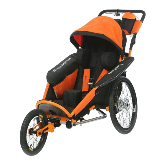
Thank you for purchasing the multifunctional xRover stroller/baby buggy and we believe that it
will serve you for a long time.
The multifunctional stroller can be used as:
1/ Standard baby buggy
2/ Bike trailer
3/ Sports baby buggy for running, inline skating, tourism, and other activities
The product complies with the following standards:
ČSN EN 1888:2012
ČSN EN 15918:2013
OPERATION MANUAL FOR
xRover – Model S
- as a baby buggy
- as a bicycle trailer
NOTICE
Please read this operation manual carefully before
using the xRover stroller/baby buggy.
1
Advertisement
Table of Contents

Summary of Contents for Volter ROXER xRover S
-
Page 1: General Description
OPERATION MANUAL FOR xRover – Model S The exclusive manufacturer and originator is the company: Volter s.r.o., ID: 29051886, E-mail: info@volter.cz Made in the Czech Republic Thank you for purchasing the multifunctional xRover stroller/baby buggy and we believe that it will serve you for a long time. -
Page 2: Description Of The Main Components Of Stroller
xRover – Model S – Description of the main components of the stroller A – height adjustable handle N – front axle, front wheels hub B – brake lever with parking lock O – 14” front wheel fork* C – foam plastic coating of handle P –... -
Page 3: Table Of Contents
CONTENTS Page General description Description of the main components of stroller Manual contents General notices Technical data Maintenance, care and storage of stroller/baby buggy Safety instructions 1. Assembly/disassembly of stroller/baby buggy 1.1 Rear axle 1.2 Front axle 2. Adjusting the required stroller/baby buggy wheel alignment 3. -
Page 4: General Notices
GENERAL NOTICES This manual contains a number of WARNINGS and NOTICES. Incorrect assembly or incorrect use of the stroller/baby buggy may lead to serious or fatal injuries of passengers or operating persons. - Car seats placed inside the stroller/baby buggy and any other seats must be fixed with additional straps. - Do not make any modifications on the stroller/baby buggy. -
Page 5: Technical Data
TECHNICAL DATA The stroller is primarily designed for transport of persons, but it can also be used for transport of loads up to the weight according to the technical data for the given size of the stroller/baby buggy. The drive or movement is provided solely by another person (other persons), preferably by pushing (at the handle of the stroller/baby buggy) or pulling (bike towing bar, towing rope fixed to the eye of front axle or towing set for summer or winter use);... - Page 6 Fork material 1: - aluminium alloy EN AW 2017 Front wheel 2: 6" Wheel material: - aluminium centre Front wheel tyre 2: - full rubber (not inflated) Front wheel fork 2: - rotating around vertical axis – suitable as a baby buggy on hard surfaces and for lower speeds Fork material 2: - aluminium alloy...
-
Page 7: Maintenance, Care And Storage Of Stroller/Baby Buggy
MAINTENANCE, CARE AND STORAGE OF STROLLER/BABY BUGGY Maintenance of the bike hitch - Before each ride make sure that the hitch and safety strap are connected properly. - Regularly check that the hitch is not damaged, broken, etc. Replace it in the case of the first sign of damage. - Any damage/break of any part of the xRover stroller/baby buggy should be repaired/replaced immediately to prevent any personal injuries. - Page 8 4. Do not modify the stroller and bike. If you are not sure whether your bike is compatible with the stroller, contact the manufacturer – Volter s.r.o. 5. Transported persons must be fixed appropriately in relation to their age, handicap or physical needs.
- Page 9 NOTICE YOU WILL ALWAYS FIND ALL IMPORTANT NOTICES ON THE STROLLER/BABY BUGGY IN THESE PLACES! MAINTENANCE SYMBOLS ARE ON EACH SEPARATE COMPONENT. THE NAMEPLATE OF THE STROLLER IS LOCATED ON THE RIGHT SIDE OF THE REAR WHEEL AXLE!
-
Page 10: Assembly/Disassembly Of Stroller/Baby Buggy
1. Assembly and disassembly of the stroller/baby buggy The stroller uses quick-acting components so both its assembly and disassembly can be performed in a few dozens of seconds. 1.1 Rear axle The rear wheels are fixed using quick-acting half-axles. By pressing the cap on one end of the axle the lock on the opposite side is released and the axle can be slid in/out the rear wheel hub. - Page 11 Insert the assembly fully into the block, release the cap and make sure that the wheel is secured in the block safely. Figure 7 Use the same procedure to install the other rear axle wheel. Both rear wheels are fully interchangeable; if you have a cyclocomputer installed, the wheel with the magnet must be installed on the left-hand side (when looking from the back).
- Page 12 1.1.2 Disassembly is to be performed in reversed order; A – grasp the rear wheel at the central hub, B – press the half-axle cap and C – fully release the wheel by pulling. Figure 9 For the subsequent transport, both dismantled rear wheels can be jointed together using one half-axle; keep the other half-axle carefully not to lose it, preferably in one of the storage bags on the stroller/baby buggy.
-
Page 13: Front Axle
1.2 Front axle The front wheels with forks are fixed to the stroller/baby buggy with quick-acting clamps. Loosen the lever to unlock the clamp, tighten it to lock the clamp; locking can be regulated by tightening or loosening the nut on the opposite end of the bolt. - Page 14 Turn the extension in the hole so that the pin (protruding dowel screw, Fig. 13 and Fig. 14, point 2) engages in the recess in the front axle block and fully slide the extension in the block. Figure 13 Figure 14 Turn both horizontal clamps to the appropriate position so that the levers do not collide with the levers of vertical clamps.
-
Page 15: Adjusting The Required Stroller/Baby Buggy Wheel Alignment
To loosen the wheel it is also necessary to loosen the nut on the opposite side of the axle by a few turns. The wheel can then be removed from the fork. The place for storing this wheel with fork is in the rear pocket of the rear bag on the stroller/baby buggy. - Page 16 The 14” front wheel can be fixed in the following range: Figure 19 – stroller seat tilt: 1 – sitting position; 2 – lying position The alignment of the rear axle must be adapted to the set tilt of the stroller/baby buggy to compensate for the possible toe-in or toe-out of the rear wheels.
- Page 17 Turn the block with the brake on the rear axle in such a way that the bubble in the built-in spirit level is between the marks. The spirit level is on the top of the block behind the brake carrier and is best accessible when looking from the back of the stroller/baby buggy.
-
Page 18: Brake Adjustment
3. Brake adjustment Both drum brakes are operated simultaneously with one double brake lever; its locking pin enables you to use the brake also as a parking brake. The brake lever is located on the handle of the stroller/baby buggy. Adjustment of the same effect of both brakes is very important to maintain the straight travel direction of the stroller/baby buggy when braking. -
Page 19: Handle
Figure 26: A – parking brake deactivated; B – parking brake activated NOTICE When you stop the stroller in traffic, always ensure that it is braked correctly! Especially when there are passengers in it and you leave the stroller without direct attendance and without the strap fixed on your wrist. -
Page 20: Hood
Figure 27 5. Hood The stroller is equipped with a removable hood to increase the comfort of transported persons and their protection against adverse environmental effects (rain, wind, snow, sunshine, etc.). The hood frame shape can be adjusted; the shape can be changed by simply pressing by hand in the required direction. Figure 28 The hood can be removed completely;... -
Page 21: Fastening The Transported Person
6. Fastening the transported person For this purpose the stroller is equipped with safety straps fixed to the frame of the stroller/baby buggy. For a better comfort, the shoulder straps are provided with soft sleeves; the position of these sleeves is adjustable from the back of the stroller/baby buggy by extending or shortening the connecting strap. - Page 22 Figure 31 8. Coupling of the stroller/baby buggy behind a bicycle The stroller may be equipped with an accessory for coupling behind a bicycle. It is comprised of the following components: 1 – towing bar for coupling on the stroller/baby buggy 2 –...
- Page 23 8.2 Tow bar of the stroller/baby buggy In ordinary use of the stroller/baby buggy, the tow bar of the stroller/buggy (if fitted permanently) is located in folded position under the stroller. The front fender is also folded and protects the lower part of the covering of the stroller/baby buggy.
-
Page 24: Coupling Of The Stroller/Baby Buggy With Bike
8.3 Coupling of the stroller/baby buggy tow bar with the bicycle hitch Grasp the stroller at the tow bar and slide the ball joint into the bike hitch from the front. For this operation it is necessary to find a suitable mutual position of the bicycle and the stroller/baby buggy so that the ball moves in the hitch freely. - Page 25 8.4 Flag The stroller must be provided with a safety flag. The fixing holes for the flag are near the hood joint on both sides of the stroller/baby buggy. Positioning the flag when the stroller/baby buggy is used in other variants than a bike stroller. Figure 39: 1 –...
-
Page 26: Other Accessories
Now the bicycle-stroller assembly is ready for use. Figure 42 9. Other accessories 9.1 Cyclocomputer – speedometer As a standard, the stroller is equipped with a wireless cyclocomputer with 8 functions. The cyclocomputer is functional both in drawing the stroller/baby buggy behind the bicycle and in pushing or drawing the stroller/baby buggy by another person. -
Page 27: Mosquito Net, Windstopper And Waterproof
The transmitting part with a motion sensor is fixed on the LEFT block of the rear axle (Fig. 21). The cyclocomputer with holder is inserted in the inner pocket in the left fender of the stroller/baby buggy allowing turning it for comfortable monitoring of the data by the transported person. The transmitting part is supplied from LR 44 batteries (2 pcs), the cyclocomputer from one CR 2032 battery. - Page 28 Figure 44 9.2.2. Windstopper The windstopper is fixed on the stroller in the same way as the mosquito net. Snap it (Fig. 43, point 2) to the outer other part of the Velcro on the hood edge. So the windstopper is stretched over the mosquito net. The order of fixing these parts can be combined arbitrarily.
- Page 29 Figure 46 The manufacturer supplies a uniform model for all S size stroller/baby buggy variants. WARNING: The windstopper protects transported persons against wind and partly against snow. However, it does not fully substitute the waterproof function and it is not water-impermeable in a longer stay in rain. 9.2.3.
-
Page 30: Rear Bag
9.3 Rear bag The rear bag serves for transport of components of the stroller (14” front wheel with fork, waterproof, mosquito net, windstopper, 6” front wheel, and others). The rear pocket of the bag is used for wheels and other “dirty” components. Use the front part of the bag for other accessories and personal items. -
Page 31: Safety Hand Strap
NOTICE Never overload the bag, it is not designed for the transport of material, only for personal items and stroller accessories. Overloading the bag could cause a turnover of the stroller/baby buggy and an injury. 9.4. Safety hand strap transportovaných pasažérů. To have a better control of the stroller/baby buggy, it is always useful to have the safety strap mounted as it prevents the possible leaving of the stroller/baby buggy away and thus it increases the control safety. - Page 32 Figure 53 1 – shoulder straps fixed on the frame tube 2 – zipper on shoulder straps Figure 54 With the upper two snaps (Fig. 54) fix the insert on the counterparts (Fig. 55) which are located on the rear side of the flap of the stroller/baby buggy seat.
-
Page 33: Winter Bag
NOTICE: When handling the stroller/baby buggy and mounting or removing the fixation insert, always follow all instructions for operation of the stroller/baby buggy. Only perform it if you are absolutely sure that the stroller/baby buggy cannot start spontaneously, overturn or otherwise threaten your baby or operating persons. 9.6. -
Page 34: Additional Bags - Hip Pack, Hand Bag
The sports hip pack can be worn also separately around the waist. It has an insulated drink bottle pocket, a double zipped pocket and a fastening strap. It can also be easily placed on the stroller/baby buggy handle. It is made in the respective colour combinations like the stroller models. - Page 35 This PRODUCT OPERATION MANUAL was issued on January 1, 2015 as version 1.1 and it is applicable until a new one is issued. The manufacturer reserves the right for changes in individual components due to the technical development of the product and accessories. Volter s.r.o., Žitná 26/570, Praha 2, 120 00, Czech Republic info@volter.cz, www.volter.cz All rights reserved.
Need help?
Do you have a question about the ROXER xRover S and is the answer not in the manual?
Questions and answers