
Subscribe to Our Youtube Channel
Summary of Contents for LAMBERT FLAPS V6 HBR (3P)
- Page 1 FLAPS_V6_HBR_datasheet_manual_EN.odt FLAPS V6 HBR (3P) (right-hand design with rotary switch and 4 LED indicators) 1/33...
- Page 2 FLAPS_V6_HBR_datasheet_manual_EN.odt Page intentionally left blank 2/33...
-
Page 3: Table Of Contents
FLAPS_V6_HBR_datasheet_manual_EN.odt Table of contents 1 Important notes and warnings...............5 2 Product description..................6 2.1 Product use......................6 2.2 Main product functionalities................6 2.3 Inputs......................6 2.4 Controls......................7 2.5 Outputs......................7 2.6 Indication......................7 2.7 Protections......................7 2.8 Description of the control panel................8 2.8.1 Control panel HBR (4 control positions)............8 2.8.2 Control panel HBR 3P (3 control positions)...........9 2.8.3 Differences between HBR and HBR 3P variants and how to read this manual when using the HBR 3P variant................10... - Page 4 FLAPS_V6_HBR_datasheet_manual_EN.odt Page intentionally left blank 4/33...
-
Page 5: Important Notes And Warnings
Responsibility for performed control actions is fully with the operator (pilot). • If you do not agree to the notes and warnings above, do not use this product. • Company LAMBERT ELECTRONIC s.r.o. reserves the right to change, improve the product or manual without prior or subsequent notice. 5/33... -
Page 6: Product Description
FLAPS_V6_HBR_datasheet_manual_EN.odt 2 Product description 2.1 Product use Product FLAPS V6 is designed for electric control of flaps of UL aircraft. It is usually supplied as a set: electronic control unit + servo motor (in case of motor without internal sensor: + position sensor + 2x protective limit switch). THIS PRODUCT APPROVED... -
Page 7: Controls
FLAPS_V6_HBR_datasheet_manual_EN.odt 2.4 Controls The flaps control unit has the following controls: rotary switch with 3 to 4 positions (depending on type) • 2 SET buttons • 2.5 Outputs The flaps control unit has the following outputs: motor power output • output to landing gear control unit (shared with dimmer signal input function) •... -
Page 8: Description Of The Control Panel
FLAPS_V6_HBR_datasheet_manual_EN.odt 2.8 Description of the control panel 2.8.1 Control panel HBR (4 control positions) position 0 with indication position 1 with indication rotary switch lever (points to the set position) SET button (UP) SET button (DOWN) position 2 with indication position 3 with indication 8/33... -
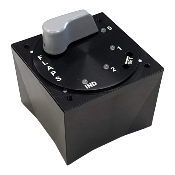
Page 9: Control Panel Hbr 3P (3 Control Positions)
FLAPS_V6_HBR_datasheet_manual_EN.odt 2.8.2 Control panel HBR 3P (3 control positions) The panel has 4 indicator LEDs, as well as the basic HBR version, but the rotary switch lever can only be rotated between positions 0 to 2. The IND position is only an indicator LED. -
Page 10: Differences Between Hbr And Hbr 3P Variants And How To Read This Manual When Using The Hbr 3P Variant
FLAPS_V6_HBR_datasheet_manual_EN.odt 2.8.3 Differences between HBR and HBR 3P variants and how to read this manual when using the HBR 3P variant The fault indication is the same as for the 4-position HBR variant • ◦ only the designation of the LED at position 3 is changed to IND in this variant, ie wherever the mention of LED 3 appears in this manual, this applies equally to IND, ie 3 = IND in firmware (FW) version 2.01 of the control unit (indicated on the nameplate,... -
Page 11: Specifications
FLAPS_V6_HBR_datasheet_manual_EN.odt 3 Specifications 3.1 Electrical characteristics Parameter Value Unit Notes Power supply voltage Vin 11 ÷ 16 Power consumption (typ) @12V power supply, stand-by state without faults, actuator stopped at the selected position, without dimming load(motor) current (max) Higner current activates overcurrent protection rated motor current Linak LA12 type the dimming voltage range at the... -
Page 12: Allowed Operating Conditions
The product is designed with regard to its intended use, for a long service life, higher than the intended service life (see below). However manufacturer LAMBERT ELECTRONIC s.r.o. HIGHLY RECOMMENDS to replace the product with a new one when it reaches its planned service life (any of the parameters below), or at the latest 10 years after purchase. -
Page 13: Tests According To Do-160G
FLAPS_V6_HBR_datasheet_manual_EN.odt 3.5 Tests according to DO-160G THIS PRODUCT APPROVED INSTALLING CERTIFIED AIRPLANES. The following tests according to DO-160G were performed on the control unit in an accredited testing laboratory, and met the criteria: Name of the test Chapter Criterion Notes Temperature and altitude Temperature Variation Shock &... -
Page 14: Installation In An Airplane
FLAPS_V6_HBR_datasheet_manual_EN.odt 4 Installation in an airplane Please pay special attention to the installation and wiring of all components of the flaps controller when installed in an airplane. This is important for the proper functioning of the equipment and the safety of the airplane. 4.1 Mechanical installation The sketch below shows the dimensions needed to fit the FLAPS V6 HBR control unit to the airplane dashboard. -
Page 15: Position Sensor Mounting
FLAPS_V6_HBR_datasheet_manual_EN.odt 4.2 Position sensor mounting If an actuator without an integrated position sensor is used in the installation, it is necessary to use an external position sensor that is rigidly mechanically attached to the actuator rod so that the control unit has undistorted actuator position information. ATTENTION! The position sensor shall be mechanically coupled so that when the piston rod is fully extended or fully retracted, the position sensor is still within its valid travel range and remains at least 5% to its edge. -
Page 16: Actuator Installation
FLAPS_V6_HBR_datasheet_manual_EN.odt 4.3 Actuator installation (POSITION 2 for HBR 3P) Observe the following points when installing the actuator: use the full mechanical travel range of the actuator piston rod to fully retract or • extract the flaps, adjust the design of the flaps control elements so that the actuator (piston rod) is retracted as much as possible with the zero flaps (position 0), with full flaps (position 3, or position 2 for HBR 3P) pulled out as far as possible... -
Page 17: Electrical Connections
FLAPS_V6_HBR_datasheet_manual_EN.odt 4.4 Electrical connections On the back of the device there is a 10-pin Molex Mini-Fit JR connector, which is used to connect the actuator, position sensor, limit switches, LBUS pin, power supply. The figure below shows a view of the back and connector with numbered pins: view of the connector in the control unit Pin no. -
Page 18: Electrical Connections Of Actuator With Internal Position Sensor And Limit Switches
FLAPS_V6_HBR_datasheet_manual_EN.odt 4.4.1 Electrical connections of actuator with internal position sensor and limit switches If the actuator you are using contains both a position sensor and limit switches, connect the control unit according to the following diagram. ATTENTION! Always refer to the documentation for the actuator used to identify the appropriate signals for the motor and position sensor. -
Page 19: Electrical Connections With Simple Actuator, External Position Sensor And Limit Switches
FLAPS_V6_HBR_datasheet_manual_EN.odt 4.4.2 Electrical connections with simple actuator, external position sensor and limit switches If your actuator does NOT include a position sensor or limit switches, it is NECESSARY TO CONNECT EXTERNAL ONES. Connect the control unit according to the following diagram, with an example of external limit switches and Honeywell RTY050 position sensor. -
Page 20: Electrical Connections For Dimming Control Unit Display Elements
FLAPS_V6_HBR_datasheet_manual_EN.odt 4.4.3 Electrical connections for dimming control unit display elements ATTENTION! Never connect the dimmer directly to the control unit (without DIMBOX accessory) !!! The control unit may be irreversibly damaged! The figure below shows the wiring diagram for dimming of the indicator elements. It shows how to connect the dimmer via DIMBOX (accessory to the FLAPS V6 HBR control unit). -
Page 21: Description Of Functions
FLAPS_V6_HBR_datasheet_manual_EN.odt 5 Description of functions 5.1 Normal mode – automatic as soon as the power is switched on, the control unit performs the initialization • sequence, which is indicated by the successive lighting of all LEDs first in red, then gradually by changing the color of each LED from red to green;... -
Page 22: Errors And Faults
FLAPS_V6_HBR_datasheet_manual_EN.odt 5.2 Errors and faults The device is able to detect various types of errors and faults. These errors and faults are indicated by LEDs and in most cases functionality of the normal (automatic) mode is blocked. In particular, the following faults are an exception: Fault Motor overcurrent •... -
Page 23: Safety Mode - Manual
FLAPS_V6_HBR_datasheet_manual_EN.odt 5.3 Safety mode – manual When the Position Sensor Fault indication is displayed and then the rotary switch is turned to either position 1 or 2, it switches to Safety (manual) mode, which is described in more detail in this section. Safety mode is indicated by steady red LEDs 1 and 2 and flashing green LEDs 0 and 3 (see following figure) The manual actuation of the flaps actuator then takes place using one of the following... -
Page 24: Device Setup Mode
FLAPS_V6_HBR_datasheet_manual_EN.odt 5.4 Device setup mode This mode is used for service setting of device functions and parameters. The device allows you to set the following parameters and functions: Functionality of the LBUS pin (landing gear control output / dimmer input) •... - Page 25 FLAPS_V6_HBR_datasheet_manual_EN.odt Indicative table of binary states (values 0 to 3, other possible values analogously): (Decimal) Value Binary Value of the Visualization of the colors of the indicator of the Parametric Parametric Option LEDs for a given Parametric Option Option 0000 0001 0010 0011...
-
Page 26: Position Programming Mode
FLAPS_V6_HBR_datasheet_manual_EN.odt 5.5 Position programming mode This mode is used to precisely set (or fine-tune pre-programmed) positions to which the actuator or the flaps connected to it are adjusted (extended and retracted). The control unit has factory preset target positions, with target position 0 corresponding to the fully retracted actuator. - Page 27 FLAPS_V6_HBR_datasheet_manual_EN.odt Repeat this sequence described above for all positions you want to program or tune. IMPORTANT NOTE: If you are reprogramming the sequence of target positions mirrored to the factory preset target positions (newly position 0 corresponds to the actuator retracted), Programmed Position Error will be displayed as soon as the first edited target position is stored on the opposite end of the piston rod path.
-
Page 28: Landing Gear Control Output
ATTENTION! The landing gear control output is intended solely for connection to the corresponding input of landing gear control unit manufactured by LAMBERT ELECTRONIC s.r.o. 5.7 Dimming of indicator elements Dimming of indicator elements is possible only if the following conditions are met: DIMBOX accessory is connected to the FLAPS V6 HBR control unit •... -
Page 29: Errors And Faults, Troubleshooting
FLAPS_V6_HBR_datasheet_manual_EN.odt 6 Errors and faults, troubleshooting 6.1 Indicated errors and faults The FLAPS V6 HBR control unit can indicate up to 4 types of serious faults. The table below lists these faults, their indications, and a more detailed description. Individual errors are indicated by orange blinking of the LED and the other LEDs are red. - Page 30 FLAPS_V6_HBR_datasheet_manual_EN.odt Indication Fault name Description & Cause Solution Motor actuator current When the switch is turned, Overcurrent has exceeded the limit the fault is reset. If this Error value. Possible causes: occurs repeatedly, do not actuator use the device until you extremely overloaded, have...
- Page 31 FLAPS_V6_HBR_datasheet_manual_EN.odt Indication Fault name Description & Cause Solution Error actuator The control unit allows the position that is higher than actuator to move without Actuator the highest programmed restriction in the inward position above target position 0. direction to the position highest This can be caused by range.
-
Page 32: Troubleshooting
FLAPS_V6_HBR_datasheet_manual_EN.odt 6.2 Troubleshooting The most common faults and their elimination are dealt with in Chapter 6.1 Indicated errors and faults, where the causes and possible remedies of the indicated errors and faults are listed in the table. However, if you do not find a solution to your fault in the that chapter, try to find the solution in the following table: Fault description Possible causes... - Page 33 Description 24.3.2020 ATAMAN Initial version 20.5.2020 ATAMAN Added information about 3-position variant HBR 3P, added info about tests www.lambertelectronic.com LAMBERT ELECTRONIC s.r.o. Phone: +420 572 522 166 Sokolovská 573 E-mail: info@lambertelectronic.com VAT:CZ28344235 68601 Uherské Hradiště www.lambertelectronic.com Czech Republic, EU 33/33...
Need help?
Do you have a question about the FLAPS V6 HBR (3P) and is the answer not in the manual?
Questions and answers