Table of Contents
Advertisement
Quick Links
RETRACTABLE TYPE FALL ARRESTER
SERVICE MANUAL
CONTENTS
1. CRW 200 Technical specification.......................................
1.1.
Description ...............................................................
1.2.
Technical data ..........................................................
1.3.
Standards .................................................................
1.4.
Identification and marking ........................................
2. Terms of servicing ..............................................................
3. Servicing equipment ..........................................................
4. Servicing operations ..........................................................
4.1. The device dismantling ..................................................
4.3. The drum set maintenance and inspection ....................
4.4 The brake set maintenance and inspection ....................
4.5. The winch unit dismantling and maintenance ................
4.6. The device rebuilding ....................................................
5. Post assembly check .........................................................
6. CRW200 - Spare parts ........................................................
edition: PROTEKT_EN-01
CRW 200
RESCUE LIFTING DEVICE
2
2
2
2
2
3
3
4
4
6
6
7
9
10
12
13
Advertisement
Table of Contents

Summary of Contents for Protect CRW 200
-
Page 1: Table Of Contents
CRW 200 RETRACTABLE TYPE FALL ARRESTER RESCUE LIFTING DEVICE SERVICE MANUAL CONTENTS 1. CRW 200 Technical specification........1.1. Description ............... 1.2. Technical data ............1.3. Standards ..............1.4. Identification and marking ........2. Terms of servicing .............. 3. Servicing equipment ............ -
Page 2: Crw 200 Technical Specification
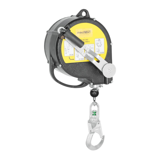
Cable diam. 4,8mm Standards EN 360:2002 EN1496:2006 – class B 1.4. Identification and marking The CRW 200 device is marked with four descriptive elements, with identification label placed on the device outer shell and repeated inside. The identification elements: Reference number •... -
Page 3: Terms Of Servicing
CRW 200 Service Manual 3/13 TERMS OF SERVICING Standard EN 365 regulates the obligation to In the event of any problems or questions, the service maintain personal protective manufacturer provides all required information equipment (PPE). Such servicing or performs the necessary testing and servicing maintenance should also be the responsibility of of the device. -
Page 4: Servicing Operations
CRW 200 Service Manual 4/13 SERVICING OPERATIONS Prior to maintenance, please ensure that all source of the problem must be identified. necessary tools, replacement parts and lubricants Carefully check whether all markings are legible. are available at hand. When servicing the... - Page 5 CRW 200 Service Manual 5/13 4.1.5 • Unscrew the bolt (10) with the aid of cross tip screwdriver. Take off the washer (11) and crank plate (12). • Unscrew the (13) bolt with the aid of Allen wrench and (14) bolt with the Allen wrench 3mm.
-
Page 6: The Retracting Spring Set Maintenance And Inspection
CRW 200 Service Manual 6/13 4.2. The retracting spring set maintenance and inspection 4.2.1 • Clean and inspect the constituent parts. Pay special attention on the retracting spring internal lubricate ending (1) shape. • Lubricate the retracting spring, using openings (1) and (2) from cable drum side. -
Page 7: The Brake Set Maintenance And Inspection
CRW 200 Service Manual 7/13 4.3.4 • Rebuild the winch set in reverse order. Pay attention on the proper installation of the cable loop (8) on the pins (9). 4.3.5 • Install the drum on the Rotating Jig. • Wind the cable by turning the drum to the right with the aid of Allen wrench 6mm (10). - Page 8 CRW 200 Service Manual 8/13 4.4.3 Unscrew the M28 nut (9). 4.4.4 Dismantle all the parts: • M28 Nut (9); • Spring washer (10); • Pressure plate (11); • Friction ring – 1 (12); • Gear (13); • Friction ring – 2 (14);...
-
Page 9: The Winch Unit Dismantling And Maintenance
CRW 200 Service Manual 9/13 4.5. The winch unit dismantling and maintenance 4.5.1 • Unscrew two M4 screws (1) with the aid of Torx type wrench T20. 4.5.2 Dismantle winch unit in the following steps: • Take off the parallel key (2). -
Page 10: The Device Rebuilding
CRW 200 Service Manual 10/13 4.6. The device rebuilding. 4.6.1 grease • Grease the main shaft (1) in the pointed place. • Mount the shaft (1) into casing. • Mount the washer (2) and Z20 snap ring (3). 4.6.2 • Mount the parallel key (4) into shaft's slot. - Page 11 CRW 200 Service Manual 11/13 glue 4.6.6 • Mount the crank (19) and glue the screws (20) and (21). Glue the screws with the aid of anaerobic adhesive. • By turning the crank to the click ... click ... click right, tight the winch brake.
-
Page 12: Post Assembly Check
CRW 200 Service Manual 12/13 POST-ASSEMBLY CHECK Under EN360 mode: • unwind the cable fully from the device, • during unwinding, pull the cable abruptly – make sure that the dogs engage, • release the cable - make sure that the cable retracts. -
Page 13: Crw200 - Spare Parts
CRW 200 Service Manual 13/13 CRW 200 - SPARE PARTS...
Need help?
Do you have a question about the CRW 200 and is the answer not in the manual?
Questions and answers