Table of Contents
Advertisement
Quick Links
How to Install Verdigris EV2
Welcome! This manual will guide you on how to install your new system. If you need
direct assistance, call our support line at 1-844-837-3447 or email support@verdigris.co.
Check out our install videos:
installEV2.verdigris.co
WARNING: Installation of Verdigris EV2 should only be performed by a licensed
electrician. You should consult your local inspector for compliance with electric codes.
If the equipment is used in a manner not specified by the manufacturer, the protection
provided by the equipment may be impaired.
Advertisement
Table of Contents

Summary of Contents for Verdigris EV2
- Page 1 Check out our install videos: installEV2.verdigris.co WARNING: Installation of Verdigris EV2 should only be performed by a licensed electrician. You should consult your local inspector for compliance with electric codes. If the equipment is used in a manner not specified by the manufacturer, the protection...
-
Page 2: Table Of Contents
Install and Connect CTs ..................................Select Appropriate CTs ………………………………………………………………………………………………………………. Verify CT Install Location ................................. Install CTs ......................................Large CTs & Verdigris High Current CT Interface Module ......................Connect Multiple CTs ..................................Connect Multiple Verdigris High Current CT Interface Modules ....................Connect CTs ……………………………………………………………………………………………………………………………. -
Page 3: Verdigris For Commercial And Industrial Buildings
• Current measurement range (Amperage): 0.25 A–15,000 A Major Steps for Installation and Commissioning Getting a Verdigris EV2 up and running consists of two parts: installation and commissioning. Both parts must be completed successfully for data to be monitored and accessible. -
Page 4: Technical Specifications
• Local Networks: BACnet/IP, Modbus/TCP Current Transformers (CTs) We offers two types of CTs: (1) Verdigris Smart CTs for censor individual circuit breakers (< 60 A) in tight spaces and (2) High Current CTs (Hinged or Coils) for larger amperage circuits. High Current CTs connect to the data chain using the Verdigris High Current CT Interface Module adapter. -
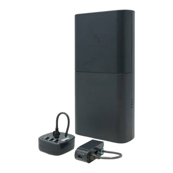
Page 5: Component List (Provided By Verdigris)
Component List (Provided by Verdigris) Verdigris High Current CT Interface Module Energy Data Gateway Verdigris Smart CT *Only for wire sizes greater than 6 AWG (1x per system) (Up to 42x per system) and/or ampacities greater than 60A (Up to 14x per system) 200mm, 1m, 3m CT 1”... -
Page 6: Tools Required
Tools Required For all installations, you will need the following tools in addition to Verdigris components: Tools • Wire stripper • Screwdrivers, including PH-2, SL-2, S-2 (needs may vary based on size of panel screws) • Impact drill (to open the panel) •... -
Page 7: Prepare Installation
Cover Plate and Top Screw. And leave 2” clearance on bottom for Ethernet port and Power Plug. Fig 2 Fig 2 CONTACT US If you are not sure where to install, call our support line at 1-844-837-3447 or email support@verdigris.co. Fig 1... -
Page 8: Select Breakers For Voltage Tap
Select Breakers For Voltage Tap Install one voltage tap on each phase of the panel. The voltage tap can be performed without shutting off any breakers if there is at least 1 spare breaker per phase. If no spare breakers are present, but there are empty slots in the panel, spare breakers can be inserted and used for the voltage tap as well. -
Page 9: Install Voltage Tap
Install Voltage Tap For Single-phase Panel For Three-Phase Panel Voltage tap using spare breakers: Voltage tap using spare breaker: 1. Ensure the breakers are turned off. Connect 1 voltage 1. Ensure the breakers are turned off. Connect 3 voltage tap cable to breaker. tap cables to breakers. -
Page 10: Connect Voltage Cables To Energy Data Gateway
Connect Voltage Cables to Energy Data Gateway • Single Phase Panel. Fig 8. Connect Neutral to ‘N’ terminal. Neutral Black Connect remaining 1 wire into ‘B’ terminal. • Split Phase Panel. Fig 9. Connect Neutral to ‘N’ terminal. Connect remaining 2 wires into ‘A’, ‘B’ terminals. Be sure to match each wire to the correct phase. -
Page 11: Install And Connect Cts
NOTE: Select the appropriate CTs for breaker ampacity. Larger amperage circuits may require the use of Large CTs in combination with high current CT interface modules. Verdigris offers the following CT sizes CONTACT US (up to 21 per chain; 42 total per system): •... -
Page 12: Large Cts & Verdigris High Current Ct Interface Module
Large CTs & Verdigris High Current CT Interface Module Large CTs can be installed around a conductor. There are Load arrow two types of CTs: hinged CTs and coil CTs. Fig 16. 1. Open the large CT: • Hinged CTs: Unlatch the CT at the opposite end of the squeeze hinge by lightly pulling up and lifting the latch. -
Page 13: Connect Multiple Cts
Fig 19 Connect Multiple Verdigris High current CT interface modules If your panel installation requires multiple high current CT interface modules: Connect the cable pigtail from the high current CT interface modules to the input port of the next high current CT interface module. -
Page 14: Connect Cts
Connect CTs Connect CT chain using extension cables and route wires through knockout into mounting bracket. Fig 21. Fig 21 IMPORTANT The maximum cable length for an entire chain loop is 8m or approximately 26ft. -
Page 15: Connect Cts To The Energy Data Gateway
Connect CTs to the Energy Data Gateway FOR INSTALLATIONS USING ONLY CT CHAINS: Using the CT extension cables to connect left & right CT chains to the corresponding & 2 female and male connectors on the Energy Data Gateway, as shown below. Fig 22. -
Page 16: Installations Using Only High Current Ct Interface Modules
FOR INSTALLATIONS USING ONLY HIGH CURRENT CT INTERFACE MODULES: Use CT extension cables, connect high current CT interface module chains to the corresponding 1 & 2 male & female connectors on the Energy Data Gateway as shown below. Fig 24. N A BC Fig 24 For installations with High Current CT Interface Module(s) on only 1 chain... -
Page 17: Installations Using Cts And High Current Ct Interface Modules
FOR INSTALLATIONS USING CTS AND HIGH CURRENT CT INTERFACE MODULES: Using CT extension cables, connect high current CT interface module/CT chains to the corresponding 1 & 2 female and male connectors on the Energy Data Gateway, as shown below. Fig 26. N A BC Fig 26 For installations with High Current CT Interface Module/CT(s) on only 1 chain... -
Page 18: System Chain Check
Green To perform the chain check procedure, the panel cover should be open. The lights on the back of the Verdigris In the event the chain light is red, the procedure described Smart CTs or the Interface Modules will indicate more here can help identify and repair any issues. -
Page 19: Steps
Steps • Check that cables are fully seated coming from the plug of the EDG to the first sensor. If any cables are found to 1. Ensure the system is powered and you can visually see be loose or not fully seated, fully insert the cable and the LEDs on the sensors. - Page 20 • Check that cables are fully seated coming from the socket C. Solid Light And Slow-Blinking Lights: of the EDG to the last sensor. If any cables are found to be loose or not fully seated, fully insert the cable and press If all the sensor lights show a mix of solid and slow blinking the “Setup”...
-
Page 21: Setup & Commission Energy Data Gateway
Sheet so that it equals the number of installed CTs per chain. Mismatches will result in inaccurate data. 5. Follow the onscreen instructions to complete the commissioning process. This process will associate each CT to an electrical circuit, and is necessary to retrieve Verdigris data from the system. Congratulations! Your Verdigris system is now installed and set-up, contact us for user access and login information. -
Page 22: Error Codes
Error Codes If you need direct assistance, call our support line at 1-844-837-3447 or email support@verdigris.co The top indicator light serves as a guide to overall system health. If the light starts blinking red, there is a problem with one or more devices within the system. The solid white means everything is good. -
Page 23: Future Panel Modifications
In the event of panel modifications or changes to the circuits you are monitoring, your Energy Data Gateway may need to be recommissioned. Please repeat steps to Commission your Energy Data Gateway and contact Verdigris for additional support at support@verdigris.co. - Page 24 NASA Ames Research Park Building 19, #1077 Moffett Field, CA 94035...
Need help?
Do you have a question about the EV2 and is the answer not in the manual?
Questions and answers