Table of Contents
Advertisement
®
SPM
Well Service Pumps & Flow Control Products
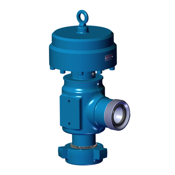
EXL Back Pressure Relief Valves
Operation Instruction and Service Manual
Copyright © 2015, S.P.M. Flow Control, Inc.. All rights reserved. S.P.M. Flow Control, Inc. is the owner of the copyright and all confidential information in
this document, which must not be copied in whole or in part, in any form or by any means, and the information in it must not be used for any purpose
other than the specific purpose for which it has been provided without the prior written consent of the copyright owner. SPM, SAFETY IRON, SAFETY
HAMMER, SUR-DROP, DESTINY, STAMPEDE, DURALAST and GLADIATOR are trademarks and/or registered trademarks of S.P.M. Flow Control,
Inc.. WEIR and WEIR (logo) are trademarks and/or registered trademarks of Weir Engineering Services Limited. Certain features of some of the products
disclosed in this document may be protected worldwide by patents pending and registered in the name of S.P.M. Flow Control, Inc..
Part Number:
2A33687
Release Date:
8/27/2015
Revision:
B
Advertisement
Table of Contents

Related Manuals for Weir SPM EXL


Summary of Contents for Weir SPM EXL
- Page 1 HAMMER, SUR-DROP, DESTINY, STAMPEDE, DURALAST and GLADIATOR are trademarks and/or registered trademarks of S.P.M. Flow Control, Inc.. WEIR and WEIR (logo) are trademarks and/or registered trademarks of Weir Engineering Services Limited. Certain features of some of the products disclosed in this document may be protected worldwide by patents pending and registered in the name of S.P.M. Flow Control, Inc..
- Page 2 Part Number: 2A33687 Release Date: 8/27/2015 Revision: THE FOLLOWING ICONS DENOTE IMPORTANT INFORMATION WITHIN THIS MANUAL. GENERAL INFORMATION INSTALLATION AND OPERATION MAINTENANCE AND REPAIR SALES AND SUPPORT NOTE CAUTION WARNING/ DANGER...
- Page 3 Company's safety policies or practices. Personal Responsibilities: ® 1. When working on Weir SPM flow control products, safety glasses, approved safety shoes and hard hat must be worn. 2. Personnel should never hammer on any component when pressure is present. Hammering on any part or component may also cause foreign material or steel slags to become airborne.
- Page 4 5. Any repairs or service (even routine maintenance) performed on the valve must be performed by a trained service technician who is qualified to work on high pressure flow control valves. All such service and repairs must be supervised by qualified management personnel or returned to Weir Oil & Gas for ®...
-
Page 5: Table Of Contents
Part Number: 2A33687 Release Date: 8/27/2015 Revision: CONTENTS SECTION I: GENERAL INFORMATION .............................. 6 : ................................6 HIS SERVICE MANUAL COVERS : ..............................6 EBUILD RITICAL OMPONENTS : ..................................7 RODUCT ESCRIPTION : ........................8 ENERAL ESCRIPTION OF ELIEF... -
Page 6: Section I: General Information
Part Number: 2A33687 Release Date: 8/27/2015 Revision: SECTION I: General Information This service manual covers: 2A33687 ASSY/RLF VA/3-1502/FULL BORE/THRD/BP Rebuild Kits/Critical Components: 2A37213 Full Kit (Metal and Seal kit) 4L28050 Metal Seal Kit (Nozzle Assembly, Valve Gate) P33637 Cartridge 2P39528 Spider... -
Page 7: Product Description
Available in 3”, this valve offers pressure ranges from 1,000 – 15,000 psi. The valve is best suited for over pressure protection in a “slick water” medium. DO NOT USE FOR H2S SERVICE! Contact your Weir Oil & Gas representative for advice about sour gas service applications. -
Page 8: General Description Of Relief Valve Operation
Part Number: 2A33687 Release Date: 8/27/2015 Revision: General Description of Relief Valve Operation: ® The SPM EXL Back Pressure Relief Valve’s operation is a simple balance between the nitrogen acting on the piston and the inlet liquid pressure acting on the rod and wear sleeve. The equation is Pressure times Area equals Force (PxA=F). -
Page 9: Section Ii: Installation And Operation
WEIR OIL & GAS HIGHLY RECOMMENDS THAT AN ISOLATION VALVE BE PLACED BETWEEN THE PRESSURE LINE AND THE RELIEF VALVE. THE ISOLATION VALVE MUST BE IN THE OPEN POSITION DURING NORMAL OPERATION. - Page 10 Part Number: 2A33687 Release Date: 8/27/2015 Revision: Installation (Cont.): At low flow rates, the valve will discharge fluid at approximately the set pressure (Fig. 2). At higher flow rates, the valve will discharge fluid at levels above the set pressure. API 520 defines the valve flow capacity as the rate that can be relieved at an over pressure of 25%.
-
Page 11: Methods To Operate Relief Valve
8/27/2015 Revision: Methods to operate Relief Valve ® Weir’s SPM EXL Relief Valve can be operated in the following ways: 1. Standard Gauges - This method uses the traditional regulators that are used to calibrate an adjacent Relief Valve. 2. Legacy Control Panel – This method encompasses the standard gauges into a control panel that can be ®... - Page 12 Part Number: 2A33687 Release Date: 8/27/2015 Revision: Standard Gauges – Calibration Guide Cont. STEP 1 Turn the Black regulator counter clockwise all the way out as shown. (B) Open the valve on the nitrogen bottle (A). The inlet gauge should indicate the pressure in the Nitrogen bottle. Verify it is over 1,000 PSI.
- Page 13 Part Number: 2A33687 Release Date: 8/27/2015 Revision: Standard Gauges – Calibration Guide Cont. STEP 3 Perform a pressure test of pumping system to the desired “Pop-off” pressure (or opening of the valve). Hold at that pressure. The “Pop-off” setting in case of an over pressure incident must be at a minimum of 1000 PSI over the system operating pressure to prevent chattering and decreased life of the valve.
- Page 14 Part Number: 2A33687 Release Date: 8/27/2015 Revision: Standard Gauges – Calibration Guide Cont. STEP 5 The use of the Tattle-tale will allow the user to indicate if there is a Nitrogen leak present during calibration. This applies to both a stand-alone Nitrogen Relief Valve and the Control Panel option. The Tattle-tale has two positions, as shown.
-
Page 15: Exl Back Pressure Relief Valve Control Panel Setting Guide (Optional)
Part Number: 2A33687 Release Date: 8/27/2015 Revision: EXL Back Pressure Relief Valve Control Panel Setting Guide (Optional) ® The Nitrogen Relief Valve can be controlled remotely through the use of the SPM Remote Control Panel. It regulates the flow of rig air or nitrogen to the relief valve and allows the operator to change pressure relief settings with the flow line. - Page 16 Part Number: 2A33687 Release Date: 8/27/2015 Revision: EXL Back Pressure Relief Valve Calibration Guide (Cont.) Values in this chart should be considered preliminary and if the predicted gas pressure does not produce the desired set pressure, you may have to adjust the regulator up or down. Some of the factors affecting performance include ambient and liquid temperature, and the gas media used.
-
Page 17: Pressure/ Temperature Ratings
Part Number: 2A33687 Release Date: 8/27/2015 Revision: Pressure/ Temperature Ratings: ® The SPM 3” EXL Back Pressure Relief Valve is available in the following configurations at this time. Part Description Working Pressure (PSI) Number 3-1502 Relief Valve Assembly EXL Back 2A33687 15,000 Pressure... -
Page 18: Section Iii: Maintenance And Repair
2. Only qualified technicians should perform maintenance on SPM products. 3. Always use Weir Oil & Gas supplied new parts kit for reassembly. 4. Clean all components thoroughly prior to reassembly. 5. Check sealing surface area of valve gate and nozzle for pitting, erosion or other flaws. Failure in sealing can result if these areas are not smooth. -
Page 19: Maintenance Requirements
An annual inspection is required to ensure that all internal components of the valve are working properly and are to Weir Oil & Gas Engineering’s specifications. It is imperative that a qualified Weir Oil & Gas Technician follow the assembly/disassembly/inspection instructions illustrated on pages 33 through 36. - Page 20 REGULAR MAINTENANCE SPARE PARTS NOTE: ALWAYS KEEP WEIR OIL & GAS SPARE PARTS ON HAND: (19, 21, 22, 26, 27) ANNUAL MAINTENANCE SPARE PARTS NOTE: ALWAYS KEEP WEIR OIL & GAS SPARE PARTS ON HAND: ALL ELASTOMER SEALS SHOULD BE REPLACED REGARDLESS OF CONDITION.
-
Page 21: Bom Table
Part Number: 2A33687 Release Date: 8/27/2015 Revision: BOM Table: PART BOM ID NUMBER DESCRIPTION P25003 LIFTING EYE 2P33647 CYLINDER 2P33754 HEX NUT 2P33645 BUMPER P21181 SHCS 2P39369 HARD STOP 2P33855 PISTON P23334 SEAL P23303 SEAL 2P37763 SPACER P23304 SEAL P23333 SEAL P23863 SHCS... - Page 22 Part Number: 2A33687 Release Date: 8/27/2015 Revision: BOM/ EXPLODED VIEW...
- Page 23 Part Number: 2A33687 Release Date: 8/27/2015 Revision: FIGURE X...
- Page 24 Part Number: 2A33687 Release Date: 8/27/2015 Revision: FIGURE Y...
-
Page 25: Preventative Maintenance And Disassembly
Part Number: 2A33687 Release Date: 8/27/2015 Revision: Preventative Maintenance and Disassembly: ENSURE ALL PRESSURE IS RELIEVED PRIOR TO PERFORMING ANY MAINTENANCE OR DISSASEMBLY! STEP 1 Remove any existing pressure on the valve! Close high-pressure N2 valve (A). Bleed down and remove N2 line to valve. - Page 26 Part Number: 2A33687 Release Date: 8/27/2015 Revision: Preventative Maintenance and Disassembly (Cont.): STEP 3 Using the Assembly Torque Tool (9) loosen the valve’s top assembly counter clockwise two (2) complete turns. This will allow for easier access to all Top Flange Fasteners (13). With an Impact Wrench (20) and 1/2”...
- Page 27 Part Number: 2A33687 Release Date: 8/27/2015 Revision: STEP 5 Once Cylinder has been removed with the crane, place it on the work table. Finish loosening the Top assembly from the Body as shown in a CCW manner. Using the Flange Lifting Tool (14) lift the top assembly off of the Body.
- Page 28 Part Number: 2A33687 Release Date: 8/27/2015 Revision: Preventative Maintenance and Disassembly (Cont.): STEP 7 Using the Flange Lifting Tool; position the assembly into the hole in the work table. Pay special care to the threading of the Flange as it is placed into position. Remove Hex Nut (3), Bumper (4), Hard Stop and Bolts (5,6), Piston and Piston Seal (7,9), and Spacer (10) from the Piston (20).
- Page 29 Part Number: 2A33687 Release Date: 8/27/2015 Revision: STEP 9 Remove the Packing Nut (18) and Packing Assembly (16) from the Flange. The Packing Assembly might require a small amount of force to remove. This can be done by tapping it from the opposite side with a bar and hammer.
-
Page 30: Preventative Maintenance: Inspecting Internal Components
Part Number: 2A33687 Release Date: 8/27/2015 Revision: Preventative Maintenance: Inspecting Internal Components BODY (36): Visually inspect the O-ring groove area beneath the seal. This is a critical area. The body will need to be replaced if any indication of wear or damage is present. Visually inspect the fluid discharge surfaces for erosion or corrosion. - Page 31 Part Number: 2A33687 Release Date: 8/27/2015 Revision: VALVE GATE AND NOZZLE: Spider (25): Visually inspect the fluid discharge areas for erosion and corrosion. Some wear is to be expected. If any damage extends deeper than .06”, then replace part. Valve gate (21) Nozzle (26), and O-ring (27): These are considered expendable items and spares should be kept on hand at all times.
-
Page 32: Preventative Maintenance: Replacement And Assembly Of Metal Sealing Components
Part Number: 2A33687 Release Date: 8/27/2015 Revision: Preventative Maintenance: Replacement and Assembly of Metal Sealing Components See “ALWAYS REMEMBER” Section on page 17 before assembly. The reassembly of the valve is in approximate reverse order to the disassembly process. Lightly lubricate all surfaces prior to assembly. OBSERVE ALL INSTRUCTIONS, CAUTIONS, AND WARNINGS AS NOTED IN THIS MANUAL. - Page 33 Part Number: 2A33687 Release Date: 8/27/2015 Revision: Preventative Maintenance: Replacement and Assembly Metal Sealing Components (Cont.) STEP 2 Insert new or polished valve gate (21) into spring retainer (33) and fit over the wave spring (22). Install the bushing (23) into the spring retainer (33). Install assembly (23), (21), (22), and (33) onto cylinder rod (20).
- Page 34 Part Number: 2A33687 Release Date: 8/27/2015 Revision: Preventative Maintenance: Replacement and Assembly Metal Sealing Components (Cont.) STEP 3 Install cylinder/ flange assembly (15) into valve body (36) by gently lowering hoist and threading clockwise. Use ® assembly torque tool (SPM 2P39525) to tighten threads until they bottom out.
- Page 35 Part Number: 2A33687 Release Date: 8/27/2015 Revision: Preventative Maintenance: Replacement and Assembly Metal Sealing Components (Cont.) STEP 4 If elbow fitting was removed, apply Teflon tape and install. Use shop air; connect air to elbow fitting and stroke the piston up and down to ensure that it moves freely. The valve is now ready for pressure testing as discussed in the “vessel testing”...
-
Page 36: Annual Maintenance: Disassembly And Repair Of Cylinder Components
Part Number: 2A33687 Release Date: 8/27/2015 Revision: Annual Maintenance: Disassembly and Repair of Cylinder Components Repeat Steps 1 through 10 referenced on the Preventative Maintenance and Disassembly Section (Pages 25 thought 29) Annual Maintenance: Inspection of internal components ROD(20): Visually inspect the piston seal areas for damage or wear. If damage or wear is evident, the part should be replaced. - Page 37 Part Number: 2A33687 Release Date: 8/27/2015 Revision: Annual Maintenance: Inspection of internal components (Cont.) FLANGE (15), PACKING ASSEMBLY/NUT (18): Visually inspect Flange (15) sealing surfaces for erosion/corrosion. Damage to this area will allow fluid to leak past the flange during the relieving function. If this surface shows signs of damage, the body should be replaced.
-
Page 38: Assembly
8/27/2015 Revision: Assembly: WARNING: THIS MAINTENANCE SECTION IS TO BE ONLY PERFORMED BY A QUALIFIED Weir Oil & Gas SERVICE TECHNICIAN! STEP 1: Install Set Screws (35) into Flange with a small amount of anti-seize. Ensure that Set Screws do not protrude opposite side of Flange (20). - Page 39 Part Number: 2A33687 Release Date: 8/27/2015 Revision: STEP 2: Using the Flange Lift Tool, position the Flange Assembly into a vise; tightening it by the packing nut. Rotate the Flange until it stops turning. This should be sufficient enough rotation on the packing. Install Flange PolyPack (12) into Flange as shown below.
- Page 40 Part Number: 2A33687 Release Date: 8/27/2015 Revision: STEP 3: Install O-rings (8, 9) into/around Piston (7). Position Hard Stop onto Piston (7) and secure with bolts (5) (Apply Anti-Seize over threads of Bolts). Slide Bumper (4) into position as shown. Lubricate ID/OD of Piston with oil.
- Page 41 Part Number: 2A33687 Release Date: 8/27/2015 Revision: STEP 4: Secure the cylinder rod (20) vertical in a vise using flats at its length. Install the spacer (10) on the rod (20). Install Top Assembly as assembled in Step 2. Secure the piston (7) and bumper (4) assembly by the hex nut (3) with blue Loctite 242 or equivalent.
- Page 42 Part Number: 2A33687 Release Date: 8/27/2015 Revision: Assembly cont. STEP 5: Insert Flange Assembly into Table hole to provide support. Ensure that the Cylinder Rod is lubricated before attempting to enter the Flange Assembly. The use of a rubber mallet may assist in installing the top to bottom assembly.
- Page 43 Part Number: 2A33687 Release Date: 8/27/2015 Revision: STEP 6: Remove Flange Hex bolts (35) and position place the Cylinder (2) onto the Flange Assembly as shown. Utilizing a Screw Nuts (5/8-11 UNC) to assist in bringing the Cylinder flush with the Flange Body.
- Page 44 Part Number: 2A33687 Release Date: 8/27/2015 Revision: Assembly cont. STEP 7: Insert new or polished valve gate (21) into spring retainer (33) and fit over the wave spring (22). Install the bushing (23) into the spring retainer (33). Install assembly (23), (21), (22), and (33) onto cylinder rod (20).
- Page 45 Part Number: 2A33687 Release Date: 8/27/2015 Revision: Assembly cont. STEP 8: Install Dowel Pins (34) into Body (36), O-Ring (27) followed by the Nozzle Assembly (26) and Spider (25). Ensure that the Spider (25) meets up with the Dowel Pins (34)
- Page 46 Part Number: 2A33687 Release Date: 8/27/2015 Revision: Assembly cont. STEP 9: Using an overhead hoist, position the Flange Assembly onto the Body as shown. Once the Threads have been engaged, use the Assembly Tool Wrench to tighten the top assembly onto the Body. Once it has stopped turning ensure that the hard stops (35) are installed.
-
Page 47: Vessel Test Procedures
Part Number: 2A33687 Release Date: 8/27/2015 Revision: Vessel Test Procedures: Prior to shipment, product testing procedure 4S12497 requires that each emergency valve pass a one-time vessel test at 150% it’s rated working pressure; then, when conducting subsequent vessel tests on used or re- certified valves, limit the pressure to 100% of rated working pressure as required by 4S12497. -
Page 48: Setting And Adjusting Pressure
ENERGIZED AND MAY CAUSE INJURY TO PERSONNEL WHEN THE VALVE RELIEVES. ERV Stand Assembly: Weir provides an ERV Stand Assembly (2A41384) for easier installation and removal of the Relief Valve on a Fracturing location. As shown in the illustration below, it is recommended that an isolation valve and a 90... -
Page 49: Troubleshooting Guide
Always follow existing Weir Oil & Gas procedures concerning identifying equipment for inspection, and removing equipment from service. The following is intended as a general guide in helping resolve most problems encountered in repairing emergency relief valves. If problems not covered here are encountered, contact Weir Oil & Gas for assistance. -
Page 50: Section Iv: Service And Support
HAMMER, SUR-DROP, DESTINY, STAMPEDE, DURALAST and GLADIATOR are trademarks and/or registered trademarks of S.P.M. Flow Control, Inc.. WEIR and WEIR (logo) are trademarks and/or registered trademarks of Weir Engineering Services Limited. Certain features of some of the products disclosed in this document may be protected worldwide by patents pending and registered in the name of S.P.M. Flow Control, Inc.. - Page 51 Headquarters: 601 Weir Way | Fort Worth, TX 76108 | Ph: +1-800-342-7458 | Fax: +1-817-977-2508 NORTH AMERICA: Houston, TX–Sales Office Rockies: LATIN AMERICA: 363 N. Sam Houston Pkwy. E., Suite 550 Billings, MT–Service Center Macae, Brazil–Service Center Houston, TX 77060...
Need help?
Do you have a question about the SPM EXL and is the answer not in the manual?
Questions and answers