Advertisement
Quick Links
Advertisement

Subscribe to Our Youtube Channel
Related Manuals for Cadence Flash F200-2


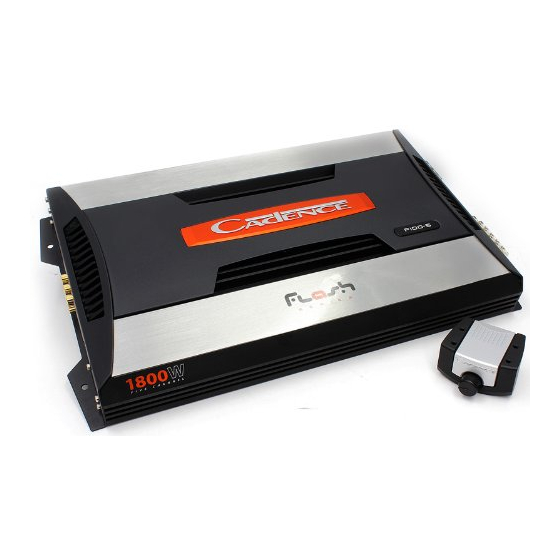
Summary of Contents for Cadence Flash F200-2
- Page 2 Drive amplifiers which are more than 16 years old. Our competition is satisfied with just continuing to build the same units year after year without thought for improvement, but not Cadence. We consider it our mission to use our expertise in developing the latest technologies and to bring you the absolute best sounding, most powerful amplifiers on the market and of course at a reasonable price.
- Page 3 (You can only imagine what they sound like.) Cadence uses only true audio transistors in the audio section of these amplifiers. These transistors were designed and engineered to produce music. That’s why Cadence amplifiers clearly sound better.
- Page 4 BATTERY VOLTAGE: Cadence Flash Series amplifiers are rated and regulated to 13.8 volts and below. Increasing voltage to 14.4 volts will increase the power output of the amplifier in the same proportion. Maximum input voltage is 14.4 volts while the minimum voltage is 12 volts.
-
Page 5: Installation Basics
Ground. amplifier screw terminal marked We recommend that you use the Cadence AMPKIT4 or AMPKIT8 amplifier installation kits, which contains all the cabling and accessories necessary for a good, reliable installation. Over the years we have received amplifiers back to our service department with melted power/ ground terminals. - Page 6 The level control of any car amplifier should not be mistaken for a volume control. It is a sophisticated device designed to match the output level of your source unit to the input level of the amplifier.
-
Page 7: Mounting And Wiring
Attach the black ground wire to the amplifier screw terminal marked Ground. We recommend that you use the Cadence AMPKIT4 or AMPKIT8 amplifier installation kits, which contains all the cabling and accessories necessary for a good, reliable installation. - Page 8 This newest series of Flash amplifiers features our newest circuitry innovation. Say for example you are trying to integrate the Cadence Flash amplifier in to a system with an OEM radio which does not have RCA output jacks or a remote...
- Page 9 RIGHT SPEAKER 2-4 OHM CROSSOVER MODE SWITCH IN FULL RANGE POSITION All Cadence Flash two channel amplifiers can accommodate either 2 ohms or 4 ohms per channel in stereo, or one 4 ohm bridged subwoofer. The diagram on this page shows a basic 2 speaker set up, for example two 6”...
- Page 10 3 CHANNEL MIXED MONO Here is how to get a three channel system out of a two channel amplifier. Crossover mode switch in Full Range. Hook up Left and Right Speakers normally as per diagram using high pass filter capacitors. Wire one subwoofer to the bridged channel utilizing a low pass filter inductor.
- Page 11 LOW PASS POSITION SUBWOOFER MINIMUM IMPEDANCE 4 OHMS When bridging Cadence two channel amplifiers, the lowest impedance for the bridged channel is 4 ohms. Set the crossover switch to Low Pass and Crossover Frequency Setting to 100 Hz as a beginning point for tuning your system.
- Page 12 4 CHANNEL AMP WITH 2 CHANNEL INPUT If your head unit has only one pair of Left and Right RCA out put jacks, plug them in to RCA input Jacks 1 and 2 of the amplifier and set the Input model switch to the 2CH position.
- Page 13 4 CHANNEL AMPLIFIER WITH 4 CHANNEL INPUT If your head unit has 2 pairs of RCA output jacks, input Front Left and Front Right in to Channels 1 and 2. Then attach radio output Rear Left and Rear Right to Channels 3 and 4. Set the Input Mode Switch to 4Ch position.
- Page 14 BAsIC FOUR CHANNEL CONFIGURATION RIGHT SPEAKER 2-4 OHM FRONT SPEAKERS LEFT SPEAKER 2-4 OHM Install any combination of speakers independently on all 4 channels being careful not to load any single channel below 2 ohm stereo. For typical 6” x 9” or 6.5”...
- Page 15 4 CHANNEL AMPLIFER BRIDGED TO 2 CHANNELS When bridging the four channel amplifier, make sure that your final woofer impedance on each bridged channel is no lower than 4 ohms. Set the Crossover Mode Switch to Low Pass and begin by setting the crossover frequency control to 100Hz and tuning from there. The dashboard bass remote control works only on channels set to Low Pass. REMOTE SUBWOOFER LEVEL CONTROL LEFT SUBWOOFER...
- Page 16 4 CHANNEL AMPLIFIER IN 3 CHANNEL MODE REMOTE SUBWOOFER LEVEL CONTROL Channels 1 and 2 should be wired to speakers no lower than 2 ohm loads per channel in stereo. Channel 3 and 4 should be bridged as per the diagram wiring the woofer to Channel CHANNEL 3-4 CONTROL ONLY 3 positive side (+) and Channel...
- Page 17 4 CHANNEL WITH MIXED MONO SUBWOOFER MINIMUM IMPEDANCE 4 OHMS LEFT SPEAKER MINIMUM SPEAKER IMPEDANCE 4 OHMS REMOTE SUBWOOFER LEVEL CONTROL CHANNEL 3-4 CONTROL ONLY FRONT SPEAKERS RIGHT SPEAKER LOW PASS FILTER INDUCTOR CH 1-2 CROSSOVER MODE SWITCH IN FULL RANGE POSITION CH 3-4 CROSSOVER MODE SWITCH IN LOW PASS POSITION SUBWOOFER...
-
Page 18: Full Range
4 CHANNEL WITH DUAL MIXED MONO CONFIGURATION ALL CROSSOVER SETTINGS IN THIS MODE SHOULD BE FULL RANGE. LEFT SPEAKER 4 OHM LEFT SPEAKER FRONT SPEAKERS MINIMUM SPEAKER IMPEDANCE 4 OHMS LOW PASS FILTER INDUCTOR REAR SPEAKERS HIGH PASS FILTER CAPACITORS RIGHT SPEAKER 4 OHM RIGHT SPEAKER... - Page 19 FIVE CHANNEL INPUT MODE If your head unit has one single pair of RCA outputs, input them in to the amplifiers Channel 1 and 2 input jacks and set the Input Mode Switch to 2Ch. The amplifiers preamp circuitry will 2 CHANNEL MODE automatically mix all the channels and output will occur on all 5 channels.
- Page 20 5 CHANNEL AMPLIFIER SPEAKER WIRING Minimum impedance for channels 1 through 4 is 2 ohm stereo. Channel five minimum impedance is 2 ohm mono capable. COMPONENT SPEAKERS MINIMUM IMPEDANCE 2-4 OHMS COMPONENT SPEAKERS MINIMUM IMPEDANCE 2-4 OHMS INPUT MODE SWITCH SET TO 5CH SUBWOOFER MINIMUM IMPEDANCE 2-4 OHMS...
- Page 21 MONO BLOCK 2 OHM AMPLIFIERS 4 OHM SUBWOOFER Models: F500-1 / 2 OHM MINIMUM LOAD F700-1 Both models F500-1 and 700-1 are 2 ohm mono block 4 OHM SUBWOOFER amplifiers. No matter how many woofers you choose to wire up to these models the final impedance should not - OR - fall below 2 ohms.
- Page 22 CLASS D MONO BLOCK 1 OHM AMPLIFIER Model: F1200-1D The F1200-1D is a 1 ohm stable mono block amplifier. It features RCA pre amp line output for feeding of a full range signal to a secondary full range amplifier in a multi-amp system. The F1200-1D also features our Integrated OEM Auto Start Sensing Circuit when used through the High Level Speaker input.
- Page 23 F1200-1D SPEAKER CONFIGURATION 2 OHM SUBWOOFER 1 OHM MINIMUM LOAD 2 OHM SUBWOOFER - OR - DVC 2 OHM SUBWOOFER IN PARALLEL = 1 OHM LOAD Model F1200-1D is a 1 ohm mono block Class D amplifier. No matter how many woofers you choose to wire up to this amplifier the final impedance load should not fall below 1 ohm.
- Page 24 F1200-1d TWIN AMPLFIER BRIDGING MASTER SWITCH SET TO MASTER MASTER / SLAVE LINK REMOTE SUBWOOFER LEVEL CONTROL SLAVE SWITCH SET TO SLAVE...
- Page 25 Make sure to use the supplied DATA CABLE for linking of the amplifiers and not the dash board bass remote cable or any other phone jack cable. If you misplace your cable, contact Cadence or your local dealer to procure a new one.
- Page 26 F1200-1d TWIN AMPLFIER BRIDGING SUBWOOFER MINIMUM IMPEDANCE 2 OHMS IMPORTANT NOTE: CONNECT THE TWO SPEAKER NEGATIVES TOGETHER WITH A #12 WIRE STRAP.
- Page 27 F1200-1d TWIN AMPLFIER BRIDGING Once again, when bridging two amplifiers together, the final impedance load of the bridged amplifiers should be no lower than 2-ohms. Double power will occur at 2-ohms. Master amplifiers positive (+) speaker terminal should be wired to the positive terminal of the subwoofer. Slave amplifiers positive (+) speaker terminal should be wired to negative terminal of the subwoofer.
-
Page 28: Specifications
SPECIFICATIONS F500-1 • Rated Power: 350 Watts RMS @ 4 ohm • Rated Power: 500 Watts RMS @ 2 ohm / 1000 Watts Peak Power • Minimum THD at Rated Power: < 0.05% • Frequency Response: 10Hz - 40KHz • S / N Ratio: >... - Page 29 SPECIFICATIONS F300-2 • Rated Power: 125 Watts RMS @ 4 ohm • Rated Power: 175 Watts RMS @ 2 ohm • Bridged Power: 350 Watts @ 4 ohm RMS Mono / 700 Watts Peak Power • Minimum THD at Rated Power: < 0.05% •...
- Page 30 SPEAKER WIRING CHART 4 X DUAL VC 8 OHM SPEAKERS WITH SERIES VOICE COILS, ALL IN PARALLEL SERIES: 4 OHM SINGLE VOICE COIL TO AMPLIFIER SPEAKERS 4 + 4 2 OHM AMPLIFIER PARALLEL: SINGLE VOICE COIL SPEAKERS 4 + 4 4 + 4 2 OHM TO AMPLIFIER...
- Page 31 2 + 2 2 OHM TO AMPLIFIER Please note that the minimum impedance load for single Cadence Flash Amplifiers is 2 ohm stereo and 4 ohm mono bridged. Lower impedance loads will cause overheating and may damage the amplifiers. Do not mix different impedance speakers in series and / or parallel combinations, as unequal power sharing and acoustic outputs will result.
- Page 32 Due to constant product improvements, these specifications are subject to change without notice. Though we tried our best to insure that this manual is free and clear of errors please don’t hold us responsible for printing errors. Copyright by Cadence Acoustics LTD.
Need help?
Do you have a question about the Flash F200-2 and is the answer not in the manual?
Questions and answers