
Summary of Contents for Rasilient ApplianceStor 30R
- Page 1 ApplianceStor 30R Performance Storage Server Rack Mount User Manual 1th Edition July 2012...
- Page 2 RASILIENT Systems, Inc. Trademarks All product names or brands mentioned herein are the trademarks of RASILIENT, its subsidiaries or other respective owners. Disclaimer This manual provides information regarding set-up and installation of the product herein.
-
Page 3: Table Of Contents
Table of Contents About This Manual 關於本手冊 ..................i Conventions 符號規範 ....................i Safety Symbols 安全性符號 ..................ii Safety Precautions 安全注意事項 ................iii Regulatory and Integration Information ..............vi Power Cords ......................viii Introduction ........................1 Audience Assumptions ....................1 About This Guide .......................1 Product introduction ......................2 System Description ....................2 New Standard ......................2... - Page 4 Rackmount rail kit ..................... 16 Attaching the rack rails ..................... 16 Chassis cover ......................20 System memory ....................... 23 Hard disk drives ......................27 Expansion slot ......................31 Setting up RAID ....................... 36 ® Intel Rapid Storage Technology Option ROM Utility ..........38 RAID driver installation .....................
- Page 5 List of Figures Figure 1 - Front panel ....................7 Figure 2 - Rear panel layout ..................8 Figure 3 - Internal view ....................9 Figure 4 - Front panel LEDs ..................10 Figure 5 - NIC LEDs ....................11 Figure 6 - Rail Kit ..................... 16 Figure 7 - Attach rails ....................
- Page 6 Figure 39 - RAID GUI ....................38 Figure 40 - Create RAID ..................39 Figure 41 - Select disk ..................... 39 Figure 42 - Create volume ..................40 Figure 43 - Create Recovery Set ................41 Figure 44 - Recovery set select disk ............... 41 Figure 45 - Recovery Set create volume ..............
- Page 7 Figure 80 - Install driver ................... 66 Figure 81 - Complete install..................66 Figure 82 - Driver Menus ..................67 Figure 83 - Utilities Menu ..................68 Figure 84 - Disk Menu ..................... 68 Figure 85 - Motherboard Layout ................71 Figure 86 - Clear RTC RAM ..................
- Page 8 Figure 121 - North Bridge ..................101 Figure 122 - South Bridge ..................101 Figure 123 - Sata Configuration ................102 Figure 124 - Intel TXT ................... 103 Figure 125 - USB configuration ................103 Figure 126 - Onboard devices ................104 Figure 127 - Serial Port Console redirect ..............
- Page 9 Hardware Installation About This Manual Conventions Safety Symbols Safety Precautions Regulatory and Integration Information User Manual ApplianceStor 30 July 2012...
-
Page 10: About This Manual 關於本手冊
About This Manual About This Manual 關於本手冊 Conventions 符號規範 To make sure that you perform certain tasks properly, take note of the following symbols used throughout this manual. 為確保您能夠正確執行特定工作,請注意本手冊中所使用的下列符號。 Provides Information to prevent injury in the process of completing a Warning: task. -
Page 11: Safety Symbols 安全性符號
About This Manual Safety Symbols 安全性符號 The following symbols are placed on some components of the system to alert the user to potential hazards, 系統的某些元件會放置下列符號,以警告使用者注意潛在危險: : Electric Shock Hazard – To reduce risk of injury from electric WARNING shock hazards, do not open this component. 警告:觸電危險-為降低可能導致觸電傷害的風險,請勿開啟本元件。... -
Page 12: Safety Precautions 安全注意事項
About This Manual Safety Precautions 安全注意事項 Technician Notes 技術人員須知 Only authorized technicians should attempt to repair this equipment. 請僅交由經授權的技術人員修理本設備。 Before installing this system, carefully read all the manuals included with the system. 在安裝本系統前,請仔細閱讀系統所隨附的各項手冊。 All repair procedures allow only module replacement. Because of the complexity of the individual boards and sub-assemblies, no one should attempt to make repairs at the component level or make modifications to any printed wiring board. - Page 13 About This Manual Keep the area free of nonconductive materials such as ordinary plastic tools and foam packing. 請清除工作區域中的所有非傳導性材質,例如一般的塑膠工具及泡棉包裝材料。 Avoid touching pins, leads, or circuitry. 請避免碰觸任何接腳、導線或電路。 Always place drives with printed circuit board (PCB) assembly-side down. 請以印刷電路板(PCB)組件側朝下放置磁碟機。 ...
- Page 14 About This Manual System Warnings Avoid dust, humidity, and extreme temperatures; place the system on a stable surface. To reduce the risk of personal injury from hot surfaces, allow the hot-plug disk modules and other system modules to cool before touching them. ...
-
Page 15: Regulatory And Integration Information
About This Manual Regulatory and Integration Information Regulatory Compliance Identification Numbers For the purpose of regulatory compliance certifications and identification, this system is assigned a serial number. This system serial number can be found on the product label, along with the required approval markings and information. When requesting certification information for this product, always refer to this serial number. - Page 16 About This Manual Communications Commission Notice Part 15 of the Federal Communications Commission (FCC) Rules and Regulations has established Radio Frequency (RF) emission limits to provide an interference-free radio frequency spectrum. Many electronic devices, including computers, generate RF energy incidental to their intended function and are, therefore, covered by these rules. These rules place computers and related peripheral devices into two classes, A and B, depending upon their intended installation.
-
Page 17: Power Cords
About This Manual EN55022 (CISPR 22) Electromagnetic Interference EN55024 (IEC61000-4-2,3,4,5,6,8,11) Electromagnetic Immunity EN61000-3-2 (IEC61000-3-2) Power Line Harmonics EN61000-3-3 (IEC61000-3-3) Power Line Flicker EN60950 (IEC950) Product Safety Canadian Notice (Avis Canadian) Table 2 - European Union Safety Requirements Class A Equipment Japanese Notice Taiwanese Notice Power Cords... - Page 18 About This Manual than the voltage and current rating marked on the product. In addition, the cross-sectional area of the wires must be a minimum of 1.00mm² or 18AWG, and the length of the cords must be between 1.8m (6 feet) and 3.6m (12 feet). If you have questions about the type of power cord to use, contact your sales representative.
- Page 19 Hardware Installation Chapter 1 Introduction Audience Assumptions About This Guide Description Features Specifications System Overview User Manual ApplianceStor 30 July 2012...
-
Page 20: Introduction
Hardware Installation Introduction Audience Assumptions This manual assumes that you are a service technician or network administrator familiar with computer hardware, data storage and network administration terminology and tasks. About This Guide This user guide provides step by step instructions on how to install, use and maintain the ApplianceStor 50 SAN Storage Server. -
Page 21: Product Introduction
PS3000 HD high performance IP storage to provide a combined optimal video surveillance solution. Rasilient there is no longer a need to worry if your VMS and cameras will work on your storage server. We prequalified and certify most major VMS solutions on our products. The AS30 cost effective, easy to install &... -
Page 22: Powerful
Introduction Powerful The AS30 is a high performance server appliance, built around high performance New Generation Intel® Sandy Bridge Xeon® quad-core processors and fast DDR3 memory. The AS30 offers high performance and bandwidth connectivity to meet the most demanding megapixel camera applications. -
Page 23: Easy
Introduction Easy AS30 provides effortless installation, management and administration. All administration functions assume technicians with basic to no storage knowledge. Once racked, setup time should be 15 minutes or less. Flexible Size Flexible design allows the AS30 to be used as a standalone in smaller Megapixel deployments; it is provided in 500GB, 2, 4, 6, and 8TB versions. -
Page 24: System Specification
Introduction System Specification Core Technology CPU Type Intel Sandy Bridge Xeon® E3-1220 Socket LGA1155 Core Logic Intel® C204 Chipset Memory size 8GB(2x4GB) Memory type DDR3 1333 ECC UDIMM Video Storage Performance Up to 640Mbs/80MBs Expansion Expansion Slot : Slot Type: PCI-E x16 (Gen2 X16 Link) (Full-Height/Half-Length) Internal slot- Storage Enhancement... -
Page 25: Table 4 - System Specification
Introduction 89/366/EEC) US (FCC, CFR47 Part 15, Class A) Europe (CE, EN55022 & EN55024) Australia (C-TICK) Taiwan (BSMI) China (CCC) Physical Characteristics Dimensions (in./mm) 24.2" x 17.5" x 1.7" 380 x 430 x 43.4 Weight 33lbs./6.5Kg Power Single Voltage 110/220V AC Watts Operating Environment Operation temperature... -
Page 26: System Layout
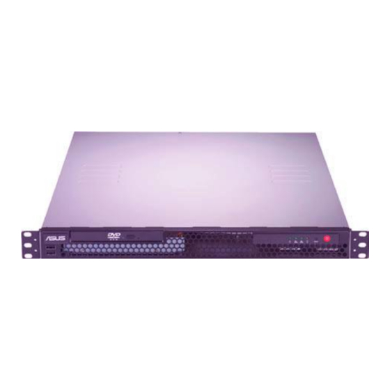
Introduction System Layout Front panel The AS30R server displays a simple yet stylish front panel with easily accessible features. The power and reset buttons, LED indicators, optical drive, and twp USB ports are located on the front panel. Figure 1 - Front panel Turn off the system power and detach the power supply before removing or replacing any system component. -
Page 27: Rear Panel
Figure 2 - Rear panel layout The ports for the PS/2 keyboard, PS/2 mouse, USB, VGA, and Gigabit LAN do not appear on the rear panel if motherboard is not present. The port is for RASILIENT SYSTEMS ASMB5-iKVM controller card only. User Manual ApplianceStor 30... -
Page 28: Internal
Figure 3 - Internal view 1. PCI Express x16 Riser Card (at x16 link) 2. System Fan (x2) (9GV0412P3J051) 3. Rasilient P8B-M Server Board 4. Power Supply 5. HDD Tray 2 (hidden) and Slim-type Optical Drive (optional) 6. HDD Tray 1 Turn off the system power and detach the power supply before removing replacing any system component. -
Page 29: Led
Introduction Front panel LEDs Figure 4 - Front panel LEDs Table 5 - LED description User Manual ApplianceStor 30 July 2012... -
Page 30: Figure 5 - Nic Leds
Introduction LAN (RJ-45) LEDs Figure 5 - NIC LEDs User Manual ApplianceStor 30 July 2012... - Page 31 Chapter 2 Before You Begin Packing Checklist...
-
Page 32: Before You Begin
1 x PCI Express x16 Riser Card (PCIE16-R11) 1 x Front I/O Board 2 x System Fans (40mm x 28mm) Accessories 1 x AS 30 Series User's Guide 1 x RASILIENT SYSTEMS Quick Start Guide User Manual ApplianceStor 30 July 2012... -
Page 33: Table 6 - Packing Checklist
Before You Begin 1 x RASILIENT SYSTEMS Auto Installation CD Guide 1 x AS 30 Series Support CD 1 x AC Power Cable 1 x Fix Rail Kit Table 6 - Packing Checklist User Manual ApplianceStor 30 July 2012... - Page 34 Hardware Installation Chapter 3 Hardware Installation Installing Hardware Modules Installing in a Rack Installing RAM, Drives and expansion boards User Manual ApplianceStor 30 July 2012...
-
Page 35: Hardware Preparation And Installation
Hardware Installation Hardware Preparation and Installation Rackmount rail kit The rack mount rail kit contains two pairs of rails (one pair for each side of the server system), six (6) pieces of inner rail screws, and two (2) pieces of rack screws. Figure 6 - Rail Kit Attaching the rack rails To attach the rack rails:... -
Page 36: Figure 8 - Attach Front Rail Nuts
Hardware Installation 2. Attach the second inner rail to the other side of the chassis and secure with three inner rail screws. 3. Select one unit of space (1U) on the rack where you wish to install the server. 4. Place three (3) nuts on the front and three at the back. Do the same to the corresponding side of the rack. -
Page 37: Figure 10 - Secure Outer Rail
Hardware Installation 7. Find the corresponding 1U space on the other side of the rack cabinet then repeat steps 5 and 6 to attach the other outer rail. Figure 10 - Secure outer rail 8. Firmly hold the server on both sides. Slide the latches on the inner rack rails to the direction indicated below. -
Page 38: Figure 12 - Push Server
Hardware Installation 9. Carefully push the server all the way to the back until the front panel fits the front end of the rack. Figure 12 - Push server 10. Secure the server to the rack with one rack screw at one side. Secure the other side as well. -
Page 39: Chassis Cover
Hardware Installation Chassis cover Removing the chassis cover Ensure that you unplug the power cord before removing the chassis cover. Take extra care when removing the chassis cover. Keep your fingers from components inside the chassis that can cause injury, such as the CPU fan, rear fan, and other sharp-edged parts. -
Page 40: Figure 15 - Lift Cover
Hardware Installation 2. Firmly hold the cover and slide it toward the rear panel for about half an inch until it is disengaged from the chassis. 3. Lift the cover from the chassis. Figure 15 - Lift cover Reinstalling the chassis cover To reinstall the chassis cover: 1. -
Page 41: Figure 17 - Slide Cover
Hardware Installation 2. Slide the cover toward the front until it snaps in place. Figure 17 - Slide cover 3. Secure the cover with three screws. Figure 18 - Secure cover User Manual ApplianceStor 30 July 2012... -
Page 42: System Memory
Hardware Installation System memory Overview The motherboard comes with six (6) Double Data Rate 3 (DDR3) Dual Inline Memory Modules (DIMM) sockets. A DDR3 module has the same physical dimensions as a DDR2 DIMM but is notched differently to prevent installation on a DDR2 DIMM socket. DDR3 modules are developed for better performance with less power consumption. - Page 43 Hardware Installation Always install DIMMs with the same CAS latency. For optimum compatibility, it is recommended that you obtain memory modules from the same vendor. User Manual ApplianceStor 30 July 2012...
-
Page 44: Figure 20 - Dimm Insertion
Hardware Installation Installing a DIMM Ensure to unplug the power supply before adding or removing DIMMs or other system components. Failure to do so may cause severe damage to both the motherboard and the components. 1. Unlock a DIMM socket by pressing the retaining clips outward. 2. -
Page 45: Figure 22 - Dimm Removal
Hardware Installation Removing a DIMM Follow these steps to remove a DIMM 1. Simultaneously press the retaining clips outward to unlock the DIMM. 2. Remove the DIMM from the socket. Figure 22 - DIMM removal Support the DIMM lightly with your fingers when pressing the retaining clips. The DIMM might get damaged when it flips out with extra force. -
Page 46: Hard Disk Drives
Hardware Installation Hard disk drives You can install up to two (2) Serial ATA hard disk drives to the system. Follow the succeeding instructions to install each of the drives. Installing a hard disk drive to the HDD tray 1 To install a hard disk drive to the HDD tray 1: 1. -
Page 47: Figure 25 - Place Drive
Hardware Installation 3. Place the hard disk drive into the HDD tray 1 matching the four screw holes with the holes on the disk drive. Figure 25 - Place drive 4. Secure the hard disk drive with four screws. Figure 26 - Secure drive Installing a hard disk drive to the HDD tray 2 To install a hard disk drive to the HDD tray 2: 1. -
Page 48: Figure 28 - Remove Screws
Hardware Installation 2. Remove the four screws to release the HDD bracket under the optical disk drive. Figure 28 - Remove screws 3. Insert the hard disk drive into the HDD bracket and secure it with four screws. Figure 29 - Insert drive 4. -
Page 49: Figure 31 - Place Hdd Bracket
Hardware Installation Use the L-type SATA connector to connect to the hard disk drive. 5. Place the HDD bracket with the hard disk drive installed into the HDD tray 2, matching the four screw holes. Then, secure the HDD bracket with four screws. Figure 31 - Place HDD bracket 6. -
Page 50: Expansion Slot
Hardware Installation Expansion slot The system comes with a riser card. You need to remove the riser card and the expansion slot bracket if you want to install an expansion card. Ensure to unplug the power cord before installing or removing an expansion card. Failure to do so may cause severe damage to the motherboard and other system components! Installing an expansion card To install an expansion card:... -
Page 51: Figure 34 - Release Metal Slot Cover
Hardware Installation 3. Remove the screw to release the metal slot cover from the expansion card bracket. Figure 34 - Release metal slot cover 4. Install the expansion card to the riser card as shown. Figure 35 - Install expansion card 5. -
Page 52: Figure 37 - Align Riser Card
Hardware Installation 6. Align the riser card with the expansion card installed to the PCI Express slot on the motherboard. 7. Press the riser card until the golden connectors completely fit the slot and the bracket aligns with the rear panel. Figure 37 - Align riser card 8. -
Page 53: Table 8 - Standard Interrupt Assignments
Hardware Installation Standard Interrupt assignments Table 8 - Standard Interrupt assignments * These IRQs are usually available for ISA or PCI devices. User Manual ApplianceStor 30 July 2012... - Page 54 Chapter 4 System Configuration RAID Setup Configure the System Additional Configuration Options User Manual ApplianceStor 30 July 2012...
-
Page 55: Setting Up Raid
System Configuration Setting up RAID ® The motherboard comes with the Intel C204 controller that supports the following SATA RAID solution: Intel Rapid Storage Technology with RAID 0, RAID 1, RAID 10, and RAID 5 support (for Windows OS only). RAID definitions (Data striping) RAID 0... - Page 56 System Configuration Installing hard disk drives The motherboard supports SATA hard disk drives for RAID set configuration. For optimal performance, install identical drives of the same model and capacity when creating a disk array. To install the SATA hard disks for RAID configuration: 1.
-
Page 57: Intel ® Rapid Storage Technology Option Rom Utility
System Configuration ® Intel Rapid Storage Technology Option ROM Utility ® The Intel Rapid Storage Technology Option ROM utility allows you to create RAID 0, RAID 1, RAID 10 (RAID 1+0), and RAID 5 set(s) from Serial ATA hard disk drives that are connected to the Serial ATA connectors supported by the Southbridge. -
Page 58: Figure 40 - Create Raid
System Configuration Creating a RAID set To create a RAID set: 1. From the utility main menu, select 1. Create RAID Volume and press <Enter>. The following screen appears. Figure 40 - Create RAID 2. Enter a name for the RAID set and press <Enter>. 3. -
Page 59: Figure 42 - Create Volume
System Configuration 5. Use the up/down arrow keys to select a drive, and then press <Space> to select. A small triangle marks the selected drive. Press <Enter> after completing your selection. 6. Use the up/down arrow keys to select the stripe size for the RAID array (for RAID 0, 10 and 5only), and then press <Enter>. -
Page 60: Figure 43 - Create Recovery Set
System Configuration Creating a Recovery set To create a recovery set: 1. From the utility main menu, select 1. Create RAID Volume and press <Enter>. The following screen appears. Figure 43 - Create Recovery Set 2. Enter a name for the recovery set and press <Enter>. 3. -
Page 61: Figure 45 - Recovery Set Create Volume
System Configuration 6. When the Sync item is selected, use the up/down arrow keys to select a sync option that you want and press <Enter>. 7. When the Create Volume item is selected, press <Enter>. The following warning message appears. Figure 45 - Recovery Set create volume 8. -
Page 62: Figure 46 - Delete Raid
System Configuration Deleting a RAID set Take caution when deleting a RAID set. You will lose all data on the hard disk drives when you delete a RAID set. To delete a RAID set: 1. From the utility main menu, select 2. Delete RAID Volume and press <Enter>. The following screen appears. -
Page 63: Figure 48 - Reset Disks
System Configuration Resetting disks to Non-RAID Take caution before you reset a RAID volume hard disk drive to non-RAID. Resetting a RAID volume hard disk drive deletes all internal RAID structure on the drive. To reset a RAID set hard disk drive: 1. -
Page 64: Figure 49 - Raid Recovery
System Configuration Recovery Volume Options If you have created a recovery set, you can configure more recovery set options following the descriptions in the section. See section Creating a Recovery set to create a recovery set before continue. To configure a recovery set: 1. -
Page 65: Figure 51 - Execute Recovery Volume
System Configuration 3. Use the up/down arrow keys to select a drive, and then press <Space> to select. A small triangle marks the selected drive. Press <Enter> after completing your selection and return to the utility main menu. Exiting the Intel® Rapid Storage Technology utility To exit the utility: 1. -
Page 66: Figure 52 - Rebuild Raid
System Configuration Figure 52 - Rebuild RAID Select a destination disk with the same size as the original hard disk. 3. The utility immediately starts rebuilding after the disk is selected. The status of the degraded RAID volume is changed to "Rebuild". Figure 53 - Select recovery disk 4. - Page 67 System Configuration 6. From the View menu, select Advanced Mode to display the details of the Intel Rapid Storage Console. 7. From the Volumes view option, select RAID volume to view the rebuilding status. When finished, the status is changed to "Normal". Rebuilding the RAID with a new hard disk If any of the SATA hard disk drives included in the RAID array failed, the system displays the status of the RAID volume as "Degraded"...
-
Page 68: Raid Driver Installation
System Configuration RAID driver installation After creating the RAID sets for your server system, you are now ready to install an operating system to the independent hard disk drive or bootable array. This part provides instructions on how to install the RAID controller drivers during OS installation. Creating a RAID driver disk The system does not include a floppy drive. -
Page 69: Figure 55 - Install Raid Driver
System Configuration 5. Use the arrow keys to select the type of RAID driver disk you want to create and press <Enter> to enter the sub-menu. C20x INTEL RAID Driver Figure 55 - Install RAID driver C20x INTEL RAID Driver Figure 56 - Select OS for RAID driver 6. - Page 70 System Configuration ® To create a RAID driver disk in Windows environment ® 1. Start Windows 2. Place the motherboard support DVD into the optical drive. 3. Go to the Makedisk menu, and then select the type of RAID driver disk you want to create. 4.
-
Page 71: Figure 57 - Install Windows Controller Driver
System Configuration Installing the RAID controller driver ® During Windows Server 2003 / XP OS installation ® To install the RAID controller driver when installing Windows Server 2003 / XP OS: Boot the computer using the Windows® Server 2003 / XP installation disc. The Windows® Setup starts. -
Page 72: Figure 59 - Insert Disk
System Configuration Insert the RAID driver disk you created earlier to the floppy disk drive, then press <Enter>. Figure 59 - Insert disk Select the RAID controller driver you need from the list, then press <Enter>. ® The Windows Setup loads the RAID controller drivers from the RAID driver disk. When prompted, press <Enter>... -
Page 73: Figure 60 - Windows 2008 Installation
System Configuration During Windows® Server 2008 OS installation To install the RAID controller driver when installing Windows® Server 2008 OS: 1. Boot the computer using the Windows® Server 2008 OS installation disc. Follow the screen instructions to start installing Windows Server 2008. 2. -
Page 74: Figure 62 - Click Browse
System Configuration 4. A message appears, reminding you to insert the installation media containing the driver of the RAID controller driver. If you have only one optical drive installed in your system, eject the Windows OS installation disc and replace with the motherboard Support DVD into the optical drive. -
Page 75: Intel® Chipset Device Software Installation
System Configuration Intel® chipset device software installation This section provides the instructions on how to install the Intel® chipset device software on the system. ® You need to manually install the Intel chipset device software on a Windows operating system. ®... -
Page 76: Figure 65 - Intel Chipset Device
System Configuration 4. The Intel(R) Chipset Device Software window appears. Click Next to start installation. Figure 65 - Intel Chipset Device 5. Select Yes to accept the terms of the License Agreement and continue the process. Figure 66 - Installer License Agreement User Manual ApplianceStor 30 July 2012... -
Page 77: Figure 67 - Installer Readme File
System Configuration 6. Read the Readme File Information and press Next to continue the installation. Figure 67 - Installer readme file 7. After completing the installation, click Finish to complete the setup process. Figure 68 - Finish chipset install User Manual ApplianceStor 30 July 2012... -
Page 78: Lan Driver Installation
System Configuration LAN driver installation ® This section provides the instructions on how to install the Intel Gigabit LAN controller drivers on the system. ® You need to manually install the LAN controller driver on a Windows operating system. To install the LAN controller drivers: Restart the computer, and then log on with Administrator privileges. -
Page 79: Figure 70 - Install Shield Wizard
System Configuration Click Next when the Intel (R)Network Connections- Install Shield Wizard window appears Figure 70 - Install Shield Wizard Toggle I accept the terms in the license agreement and click Next to continue Figure 71 - Install Wizard read me User Manual ApplianceStor 30 July 2012... -
Page 80: Figure 72 - Select Options
System Configuration Click the Intel(R) PROSet for Windows Device Manager box, and then click Next to start the installation. Figure 72 - Select options Follow the screen instructions to complete installation Figure 73 - Install driver User Manual ApplianceStor 30 July 2012... -
Page 81: Figure 74 - Install Finish
System Configuration When finished, press Finish to continue. Figure 74 - Install finish User Manual ApplianceStor 30 July 2012... -
Page 82: Vga Driver Installation
System Configuration VGA driver installation This section provides the instructions on how to install the ASPEED Video Graphics Adapter (VGA) driver. You need to manually install the ASPEED VGA driver on a Windows® operating system. To install the ASPEED VGA driver: Restart the computer, and then log on with Administrator privileges. -
Page 83: Figure 76 - Video Install Shield
System Configuration Click Next to start the installation. Figure 76 - Video Install shield Toggle I accept the terms in the license agreement and click Next to continue. Figure 77 - License Agreement User Manual ApplianceStor 30 July 2012... -
Page 84: Figure 78 - Customer Information
System Configuration Enter the user information and click Next to continue. Figure 78 - Customer information Select a setup type and click Next to continue. Figure 79 - Install type User Manual ApplianceStor 30 July 2012... -
Page 85: Figure 80 - Install Driver
System Configuration Click Install to start driver installation. Figure 80 - Install driver When the installation completes, click Finish to restart your computer before using the program. Figure 81 - Complete install User Manual ApplianceStor 30 July 2012... -
Page 86: Management Applications And Utilities Installation
The support DVD that came with the motherboard package contains the drivers, management applications, and utilities that you can install to avail all motherboard features. The contents of the support DVD are subject to change at any time without notice. Visit the RASILIENT SYSTEMS website at www.rasilient.com for updates. -
Page 87: Figure 83 - Utilities Menu
The Make disk menu contains items to create the Intel Rapid Storage Technology driver disks. Figure 84 - Disk Menu Contact information Click the Contact tab to display the RASILIENT SYSTEMS contact information. You can also find this information on the inside front cover of this user guide. User Manual... - Page 88 System Configuration Rasilient Contact Information US Office: RASILIENT Systems, Inc. 3281 Kifer Road Santa Clara, CA 95051 Tel: 1 (408) 800-7301 Shanghai Office: RASILIENT Systems, Inc. 498 Guo Shou Jing Rd. Pudong Software Park Building 10, 2nd floor Shanghai 201203, China 上海市郭守敬路...
- Page 89 Chapter 5 Advanced System Use and Maintenance Mother board Jumpers Connectors LEDs BIOS User Manual ApplianceStor 30 July 2012...
-
Page 90: Advanced System Use And Maintenance
Advanced System Use & Maintenance Advanced System Use and Maintenance Motherboard Layout Figure 85 - Motherboard Layout User Manual ApplianceStor 30 July 2012... -
Page 91: Jumpers
Advanced System Use & Maintenance Jumpers Clear RTC RAM (CLRTC1) This jumper allows you to clear the Real Time Clock (RTC) RAM in CMOS. You can clear the CMOS memory of date, time, and system setup parameters by erasing the CMOS RTC RAM data. The onboard button cell battery powers the RAM data in CMOS, which include system setup information such as system passwords. -
Page 92: Figure 87 - Vga Controller
Advanced System Use & Maintenance VGA controller setting (3-pin VGA_SW1) This jumper allows you to enable or disable the onboard VGA controller. Set to pins 1-2 to activate the VGA feature. Figure 87 - VGA controller CPU Fan and Chassis Fan control setting (3-pin CPUFAN_SEL1, CHAFAN_SEL1) These jumpers allow you to switch for fan pin selection. -
Page 93: Figure 89 - Lan Controller
Advanced System Use & Maintenance LAN controller setting (3-pin LAN_SW1, LAN_SW2) These jumpers allow you to enable or disable the onboard Intel® 82574L Gigabit LAN controllers. Set to pins 1-2 to activate the Gigabit LAN feature. Figure 89 - LAN controller RAID configuration utility selection (3-pin RAID_SEL1) This jumper allows you to select the RAID configuration utility to use when you create disk arrays. -
Page 94: Figure 91 - Force Bios Recovery
Advanced System Use & Maintenance Force BIOS recovery setting (3-pin RECOVERY1) This jumper allows you to quickly update or recover the BIOS settings when it becomes corrupted. To update the BIOS: 1. Prepare a USB flash disk that contains the original or latest BIOS for the motherboard (XXXXXX.ROM) and the BUPDATER.EXE utility. -
Page 95: Connectors
Advanced System Use & Maintenance Connectors Chassis intrusion connector (2 pin CHASSIS) This connector is for a chassis-mounted intrusion detection sensor or switch. Connect one end of the chassis intrusion sensor or switch cable to this connector. The chassis intrusion sensor or switch sends a high-level signal to this connector when a chassis component is removed or replaced. -
Page 96: Internal Connectors
Advanced System Use & Maintenance Internal connectors Serial ATA connectors (SATA 6Gbs: 7-pin SATA1, SATA2 [Blue]) (SATA 3Gbs: 7-pin SATA3, SATA4, SATA5, SATA6 [Black]) Supported by the Intel® C204 chipset, these connectors are for the Serial ATA signal cables for Serial ATA hard disk drives that allows up to 6Gb/s of data transfer rate. -
Page 97: Figure 95 - Hard Disk Activity Led
Advanced System Use & Maintenance Hard disk activity LED connector (4-pin HDLED1) This LED connector is for the storage add-on card cable connected to the SATA or SAS add-on card. The read or write activities of any device connected to the SATA or SAS add-on card causes the front panel LED to light up. -
Page 98: Figure 97 - Cpu, Front And Rear Fan Connectors
Advanced System Use & Maintenance CPU, front and rear fan connectors (4-pin CPU_FAN1, FRNT_FAN1, FRNT_FAN2, FRNT_FAN3, REAR_FAN1) The fan connectors support cooling fans of 350 mA-740 mA (8.88 W max.) or a total of 3.15 A-6.66 A (53.28 W max.) at +12V. Connect the fan cables to the fan connectors on the motherboard, ensuring that the black wire of each cable matches the ground pin of the connector. -
Page 99: Figure 99 - Thermal Sensor
Advanced System Use & Maintenance Thermal sensor cable connectors (3-pin TR1) This connector is for temperature monitoring. Connect the thermal sensor cable to this connector and place the other end to the device, which you want to monitor temperature. Figure 99 - Thermal sensor You can connect the thermal sensor cable to either pin 1-2 or pin 2-3. -
Page 100: Figure 101 - Bmc Header
Advanced System Use & Maintenance BMC header (BMC_FW1) The BMC connector on the motherboard supports an RASILIENT SYSTEMS® Server Management Board 5 Series (ASMB5). Figure 101 - BMC header Power Supply SMBus connector (5-pin PSUSMB1) This connector allows you to connect SMBus (System Management Bus) to the power supply unit to read PSU information. -
Page 101: Figure 103 - Tpm Connector
Advanced System Use & Maintenance TPM connector (20-1 pin TPM) This connector supports a Trusted Platform Module (TPM) system, which can securely store keys, digital certificates, passwords, and data. A TPM system also helps enhance network security, protects digital identities, and ensures platform integrity. Figure 103 - TPM connector ATX power connectors (24-pin ATXPWR1, 8-pin ATX12V1) These connectors are for an ATX power supply plugs. -
Page 102: Figure 104 - Atx Power
Advanced System Use & Maintenance Figure 104 - ATX power System panel connector (20-pin PANEL1) This connector supports several chassis-mounted functions. Figure 105 - System panel 1. System power LED (3-pin PLED) This 3-pin connector is for the system power LED. Connect the chassis power LED cable to this connector. -
Page 103: Figure 106 - Auxiliary Panel
Advanced System Use & Maintenance 4. Hard disk drive activity LED (2-pin HDDLED) This 2-pin connector is for the HDD Activity LED. Connect the HDD Activity LED cable to this connector. The IDE LED lights up or flashes when data is read from or written to the HDD. - Page 104 Advanced System Use & Maintenance 4. Locator LED (2-pin LOCATORLED1 and 2-pin LOCATORLED2) These leads are for the locator LED1 and LED2 on the front panel. Connect the Locator LED cables to these 2-pin connector. The LEDs will light up when the Locator button is pressed. 5.
-
Page 105: Bios Configurations
The following utilities allow you to manage and update the motherboard Basic Input/output System (BIOS) setup: 1. RASILIENT SYSTEMS CrashFree BIOS 3 (To recover the BIOS using a bootable USB flash disk drive when the BIOS file fails or gets corrupted.) 2. -
Page 106: Figure 107 - Ez Flash Gui
RASILIENT SYSTEMS website at www.rasilient.com to download the latest BIOS file. RASILIENT EZ Flash Utility The RASILIENT EZ Flash Utility feature allows you to update the BIOS without having to use a DOS-based utility. Visit the RASILIENT SYSTEMS website at www.rasilient.com to download the latest BIOS file. - Page 107 Updating the BIOS file To update the BIOS file using the BUPDATER utility: Visit the RASILIENT SYSTEMS website at www. Rasilient.com and download the latest BIOS file for the motherboard. Save the BIOS file to a bootable USB flash disk drive.
-
Page 108: Figure 108 - Bupdater
Advanced System Use & Maintenance Figure 108 - BUPdater 4. The utility verifies the file, and then starts updating the BIOS file. Figure 109 - BIOS updater DO NOT shut down or reset the system while updating the BIOS to prevent system boot failure! 5. -
Page 109: Bios Setup Program
Yes to load the BIOS default settings. The BIOS setup screens shown in this section are for reference purposes only, and may not exactly match what you see on your screen. Visit the RASILIENT SYSTEMS website at www.rasilient.com to download the latest BIOS file for this motherboard. -
Page 110: Figure 111 - Bios Screen
Advanced System Use & Maintenance BIOS menu screen Figure 111 - BIOS screen Menu bar The menu bar on top of the screen has the following main items: Main For changing the basic system configuration Event Logs For changing the event log settings Advanced For changing the advanced system settings Monitor... - Page 111 Advanced System Use & Maintenance Menu items The highlighted item on the menu bar displays the specific items for that menu. For example, selecting Main shows the Main menu items. The other items (Event Logs, Advanced, Monitor, Boot, Tool, and Exit) on the menu bar have their respective menu items.
-
Page 112: Main Menu
Advanced System Use & Maintenance Main menu When you enter the BIOS Setup program, the Main menu screen appears. The Main menu provides you an overview of the basic system information, and allows you to set the system date, time, language, and security settings. Figure 112 - BIOS Main System Date [Day xx/xx/xx] Allows you to set the system date. - Page 113 Advanced System Use & Maintenance If you have forgotten your BIOS password, erase the CMOS Real Time Clock (RTC) RAM to clear the BIOS password. See section Jumpers page 64 for information on how to erase the RTC RAM. The Administrator or User Password items on top of the screen show the default Not Installed.
-
Page 114: Event Logs Menu
Advanced System Use & Maintenance To change a user password: Select the User Password item and press <Enter>. From the Enter Current Password box, key in the current password, then press <Enter>. From the Create New Password box, key in a new password, then press <Enter>. Confirm the password when prompted. - Page 115 Advanced System Use & Maintenance Erase Event Log [No] Allows you to select the options for erasing Smbios event log. Configuration options: [No] [Yes, Next reset] [Yes, Every reset] When Log is Full [Do Nothing] Allows you to select the options for reaction when the event logs are full. Configuration options: [Do Nothing] [Erase Immediately] MECI pod Allows you to adjust value for the MECI (Multiple Event Count Increment),...
-
Page 116: Advanced Menu
Advanced System Use & Maintenance Advanced menu The Advanced menu items allow you to change the settings for the CPU and other system devices. Take caution when changing the settings of the Advanced menu items. Incorrect field values can cause the system to malfunction. Figure 116 - Advanced setting ACPI Settings Figure 117 - ACPI Settings... -
Page 117: Figure 118 - Tmp
Advanced System Use & Maintenance Trusted Computing Figure 118 - TMP TPM SUPPORT [Disabled] Allows you to enable or disable the TPM support. Configuration options: [Disabled] [Enabled] WHEA Configuration Figure 119 - WHEA WHEA Support [Enabled] Allows you to enable or disable the Windows Hardware Error architecture support. Configuration options: [Disabled] [Enabled] User Manual ApplianceStor 30... -
Page 118: Figure 120 - Cpu Settings
Advanced System Use & Maintenance CPU Configuration The items in this menu show the CPU-related information that the BIOS automatically detects. Some items may not appear if your CPU does not support the related functions. Figure 120 - CPU settings Intel Adaptive Thermal Monitor [Enabled] Allows you to enable or disable the CPU thermal monitor function. - Page 119 Advanced System Use & Maintenance Execute Disable Bit [Enabled] Allows you to enable or disable the No-Execution Page Protection Technology. Setting this item to [Disabled] forces the XD feature flag to always return to zero (0). Configuration options: [Disabled] [Enabled] Intel Virtualization Tech [Enabled] The Intel®...
-
Page 120: Figure 121 - North Bridge
Advanced System Use & Maintenance North Bridge The North Bridge is built in the CPU. Figure 121 - North Bridge Low MMIO Align [64M] Allows you to select the options for the Low MMIO Align. Configuration options: [64M] [1024M] DMI Gen2 [Enabled] Allows you to enable or disable the DMI Gen2. -
Page 121: Figure 123 - Sata Configuration
Advanced System Use & Maintenance SATA Configuration While entering Setup, the BIOS automatically detects the presence of SATA devices. The SATA Port items show Not Present if no SATA device is installed to the corresponding SATA port. Figure 123 - Sata Configuration SATA Mode [IDE Mode] Allows you to set the SATA configuration. -
Page 122: Figure 124 - Intel Txt
Advanced System Use & Maintenance Serial-ATA Controller 1 [Enhanced] This item appears only when you set the SATA Mode item to [IDE Mode]. Set to [Enhanced] to support two SATA 3.0 Gb/s devices. Configuration options: [Disabled] [Enhanced] S.M.A.R.T. Status Check [Enabled] S.M.A.R.T. -
Page 123: Figure 126 - Onboard Devices
Advanced System Use & Maintenance The USB Devices item shows the auto-detected values. If no USB device is detected, the item shows None. Legacy USB Support [Enabled] Allows you to enable or disable support for legacy USB devices. Setting to [Auto] allows the system to detect the presence of USB devices at startup. - Page 124 Advanced System Use & Maintenance INTEL W82574L OpROM1/OpROM2 [PXE] Allows you to select the options for the Option Rom of the Intel LAN controllers. Configuration options: [Disabled] [PXE] [iSCSI] Serial Port 1/2 Configuration The sub-items in this menu allow you to set the serial port 1/2 configuration. Serial Port [Enabled] Allows you to enable or disable the serial port (COM).
-
Page 125: Figure 127 - Serial Port Console Redirect
Advanced System Use & Maintenance Power On By PCIE [Disabled] [Disabled] Disables the PCIE devices to generate a wake event. [Enabled] Enables the PCIE devices to generate a wake event. Power On By Ring [Disabled] [Disabled] Disables Ring to generate a wake event. [Enabled] Enables Ring to generate a wake event. - Page 126 Advanced System Use & Maintenance Terminal Type [VT-UTF8] Allows you to set the terminal type. [VT100] ASCII char set. [VT100+] Extends VT100 to support color, function keys, et. [VT-UTF8] Uses UTF8 encoding to map Unicode chars onto 1 or more bytes [ANSI] Extended ASCII char set Bits per second [57600]...
-
Page 127: Figure 128 - System Monitor
N/A. Fan Speed Control [Generic Mode] Allows you to configure the RASILIENT SYSTEMS Smart Fan feature that smartly adjusts the fan speeds for more efficient system operation. Configuration options: [Full Speed Mode] [High Density Mode] [Generic Mode] [Whisper Mode]... -
Page 128: Boot Menu
Allows you to select the power-on state for the NumLock. Configuration options: [Off] [On] Full Screen Logo [Enabled] Allows you to enable or disable the full screen logo display feature. Configuration options: [Disabled] [Enabled] Set this item to [Enabled] to use the RASILIENT SYSTEMS MyLogo2™ feature. User Manual ApplianceStor 30 July 2012... - Page 129 To select the boot device during system startup, press <F8> when RASILIENT SYSTEMS Logo appears. To access Windows OS in Safe Mode, do any of the following: - Press <F5> when RASILIENT SYSTEMS Logo appears.Press <F8>...
-
Page 130: Tool Menu
<Enter> to display the submenu. Figure 12 - EZ Flash Rasilient Systems EZ Flash Utility Allows you to run RASILIENT SYSTEMS EZ Flash BIOS ROM Utility when you press <Enter>. Check section RASILIENT SYSTEMS EZ Flash Utility for details. Exit menu The Exit menu items allow you to save or discard your changes to the BIOS items. - Page 131 Advanced System Use & Maintenance Discard Changes & Exit This option allows you to exit the Setup program without saving your changes. When you select this option or if you press <Esc>, a confirmation window appears. Select Yes to discard changes and exit.
Need help?
Do you have a question about the ApplianceStor 30R and is the answer not in the manual?
Questions and answers