
Related Manuals for SOFTLINK WB169-430

Summary of Contents for SOFTLINK WB169-430
- Page 1 WIRELESS COMMUNICATION SYSTEM Wireless M-Bus WB169-430 Revision 1.0 SOFTLINK s.r.o., Tomkova 409, 278 01 Kralupy nad Vltavou, Czech Republic Phone.: +420 315707111, e-mail: sales@softlink.cz, www.softlink.cz...
-
Page 2: Table Of Contents
......Structure of Wireless M-BUS message header of the WB169-430 module .... - Page 3 ” Form for setting of basic parameters and list of watermeters in reach acquired by RADAR function View of WB169-430 module information message received by WMBUSAN4 analyzer ..Encrypted and decrypted message of the WB169-430 module .
-
Page 4: Introduction
” As the receiver of the WB169-430 module is used for receiving of watermeter messages, back channel features cannot be used for this type of device. Module usage The WB169-430 module can be used as a local communication gateway for remote reading of Sensus iPERL-series watermeters. -
Page 5: Hardware Features And Power Supplying
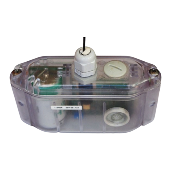
The module can be controlled and configured either by configuration cable, or wirelessly, by infra-red optical converter. The module is equipped with the special circular aperture (”peephole”) for magnetic fixing of the optical converter. External appearance of the WB169-430 module is shown in the figure 1. Figure 1: View of the WB169-430 module WB169-430... -
Page 6: Technical Parameters Overview
Technical parameters overview Overview of WB169-430 module technical parameters is shown in the Table1 below. Table 1: Overview of WB169-430 module technical parameters RF subsystem parameters Frequency band * 169.40625 to 169.46875 Modulation * 2-GFSK, 4-GFSK Bandwidth * 12.5 or 50... -
Page 7: Configuration Of The Wb169-430 Module
Setting of WB169-430 module parameters by configuration cable In following part of the document there is a description of these parameters of the WB169-430 module, that can be displayed and examined from PC connected to the module by configuration cable. Some of the parameters can be changed by configuration commands entered... - Page 8 : Show this help mon# Overview of configuration parameters with short description of their meaning can be also found in table on the page 17. The meaning of individual parameters and detailed description of their usage can be found below. WB169-430...
-
Page 9: Commands For Writing Of Configuration And Reset
FLASH memory by ”clean” command. This command is recommended to use only by users with good knowledge of the system or after consultaion with the manufacturer. The module reset can be performed by using of ”reset” command. WB169-430... -
Page 10: Wmbus" Group Commands For Setting Of Messages
M-BUS ID” is a serial number of the device in M-Bus standard identification system. The address is ” read only” type for the WB169-430 module and cannot be changed. Assigned serial number of the module can be ” displayed by mid”... - Page 11 Wireless M-BUS standard, accurate choice of relevant communication modes of the module is stated in the line ”mode” of ”Help” summary (see the paragraph 3.1). An example of checking, setting and re-checking of communication mode: WB169-430...
- Page 12 (see chapter 3.1.1) Encryption can be switched off by setting of ”.” (dot) parameter after the ekey“ command: ” cfg#ekey. Encyption disabling cfg# In this case an information Data will be unencrypted” appears in the list of configuration parameters. ” WB169-430...
-
Page 13: Commands For Setting Of Watermeter Reading
Recv ID 130551475, Val 0, status 0, rssi -63 Recv : 00 d1 07 c8 0e b1 97 97 97 97 97 ea f2 89 ....Recv ID 130551473, Val 0, status 0, rssi -88 Recv : . . . WB169-430... -
Page 14: Commands Of " Utils" Group For Setting Of Module Common Functions
The ”Set Sensus meter ID” variable serves for setting of list of Sensus iPERL watermeters, that is intended to be read by the WB169-430 module. Each record to the list could be created by using of ”sid [index] [value]” command, where meter ID (serial number) is linked with meter index (0 - 9). - Page 15 first message is transmitted immediately. Number of messages in the series is set by ”number” parameter after command, where maximum number of messages in series is 30. This command can be used during installation and testing of the module. An example of the command for sending of series of 5 messages: WB169-430...
-
Page 16: Displaying Of Other Operational Entries In The List Of Parameters
(as well MBUS-ID in M-Bus address) HW Version hardware version by manufacturer HW Revision hardware revision by manufacturer SW Version software version by manufacturer SW Revision software revision by manufacturer Manufacturer MBUS Manufacturer code Version MBUS-Version in M-Bus address WB169-430... -
Page 17: Wb169-430 Module Configuration Table
”Medium” parameter is an international code of measured energy, water or other medium according to the M-Bus coding system. The value of the parameter is editable for the WB169-430 (it is an editable part of full meter/sensor M-Bus identification), the default value of the Medium”... - Page 18 The ”Sensus ID” is a list of Sensus iPERL watermeters, that are intended to be read by the WB169-430 module. It contains 5 editable fields (index 1 - 5), where watermeter IDs (serial numbers) can be preset. Any received messages. Received messages from any other watermeters (that are not in the table) are ignored.
-
Page 19: Configuration Forms Of Wb169-430 Module In Softlink Configurator" Application
- switching of RADAR mode for 60 seconds (LAUNCH RADAR) - displaying of RADAR function results (RESULTS) - sending of RESET command to the module As the SOFTLINK Configurator” application is continuously developed and improved, the screen previews of ” WB169-430 module configuration forms can vary in time. WB169-430... -
Page 20: Overview Of Module Configuration Parameters
3.2.1 Overview of module configuration parameters Overview of configuration parameters that can be used for user settings of the WB169-430 module is shown in the Table below. The parameters are presented in the same order as they appear in the List of all configuration parameters (see paragraph 3.1.1). -
Page 21: Structure Of Module Data Messages
”INFO” field). Structure of Wireless M-BUS message header of the WB169-430 module is described in the Table 3. Table 3: Structure of Wireless M-BUS message header of the WB169-430 module... -
Page 22: View Of Wb169-430 Module Information Message Received By Wmbusan4 Analyzer
32, 48, 64...etc. Bytes). Rounding of the message is performed by inserting of required number of ”2F” blocks. Decoded encrypted message of the WB169-430 module with two control segments at the beginning and several other ”2F” blocks at the end is shown in the Figure 6. This way the length of message data block is rounded to 64 Byte. -
Page 23: Alarm Message
Alarm message Alarm message of the module is transmitted immediately after some of the supported alarm types arises. Current modification of WB169-430 module supports one type of event - information about the module reset, with additional information about its type/cause. -
Page 24: Operational Conditions
Operational conditions This section of the document describes basic recommendations for transportation, storing, installation and operation of WB169-430 radio modules. General Operation Risks The radio modules are electronic devices power-supplied by internal batteries. The modules read counters or registers of the connected consumption meters. -
Page 25: The Condition Of Modules On Delivery
(with exception of modules with additional sealing by silicon filling - see paragraph 4.2). Safety precautions Warning! Mechanical and electrical installation of the WB169-430 module can be provided only by a person with necessary qualification in electrical engineering. Environmental protection and recycling The equipment contains non-rechargeable lithium battery. -
Page 26: Set Of Wb169-430 Module Components With Rod Antenna
Figure 8: Set of WB169-430 module components with rod antenna In the figure there is displayed the detail of WB169-430 module printed circuit board with configuration connector marked by red colour, antenna connector marked by blue colour and battery switch marked by green colour. -
Page 27: Module And Meter Replacement
– the base and the cap together. The correct module completion can be checked out according to the auxiliary label with the serial number glued on the PCB. When there is necessary to replace a consumption meter read by the module due to the meter failure, expired metrology period or for any other reason, follow this procedure: WB169-430... -
Page 28: Module Dismantling
(RSSI = Received Signal Strength Indicator) If the Radar” table is displayed in a sufficiently long time since the WB169-430 module was putting into operation ” (or since its rebooting), the table should contain reports from meters and sensors connected to the module, including the evaluation of the receiving quality. -
Page 29: Troubleshooting
Troubleshooting Possible causes of module failures If during operation of WB169-430 module some anomaly, malfunctions or other troubles are recognized, the possible causes of the failures can be classified by following categories: 5.1.1 Power supplying failures The module is supplied by electrical power from the long-life internal battery. -
Page 30: System Failures
Attenuation of the signal can be caused by making of some change in module installation site (e.g. turning of antenna or placing of some object nearby, installation of iron bars, rack or shelfs...) or similar WB169-430... -
Page 31: Failures Of Communication With Watermeters
To identify a reason of device failure or any anomaly in its operation follow this procedure: 1. No data are available from any watermeter read by the WB169-430 module. In this case it is recommended to check functionality of the module subsystems in following order: check correctness of setting of the module in the central system database;... -
Page 32: Additional Information
Additional information This manual is focused on description, parameters and configuration options of radio modules WB169-430, operating according to the Wireless M-BUS standard (EN 13757-3 / EN 13757-4 recommendation) for the 169 MHz band, that are a part of the Softlink’s wacoSystem product family. More information about all WB169 (Wireless M-BUS), WM868 (WACO), WS868 (Sigfox) or NB (NB-IoT) series of the modules can be found on the manufacturer website: www.wacosystem.com...
Need help?
Do you have a question about the WB169-430 and is the answer not in the manual?
Questions and answers