Table of Contents
Advertisement
Advertisement
Table of Contents

Summary of Contents for Pulse fitness 260G
- Page 1 260G Assembly, Operation & Parts Manual (Reference) EU/US...
- Page 2 Company Addresses Global Corporate Headquarters Regional (Distributor/Dealer) Address(es) Address: Current List of Distributors/Dealers: Pulse Fitness Ltd., Radnor Park, Greenfield Road, Congleton, https://www.thepulsegroup.co.uk/pulse-global Cheshire, CW12 4TW, England, United Kingdom Sales/Marketing: Americas Tel: +44 (0)1260 294600 North America Fax: +44 (0)1260 299282 Email: info@pulsefitness.com...
- Page 3 This manual describes the equipment's setup its installation and instructs how to use it correctly and safely. It is of the utmost importance that any User of the PULSE FITNESS Run (Low Impact 'Elevation' Treadmill) is fully trained in its operation! Please ensure that the instructions given in General Safety Precautions section are understood by ALL Users.
- Page 4 Overview (Continued) Statement of Purpose: The treadmill is an exercise machine that enables users to walk or run, in place, on a moving surface. FCC Warning - Possible Radio / Television Interference. NOTE: This equipment has been tested and found to comply with the limits for a Class A digital device, pursuant to part 15 of the FCC rules.
-
Page 5: Table Of Contents
Table of Contents 260G Overview Connections to Power Supply 7.1 Wiring the Motor Contents of 260G Flat Pack Important Safety Instructions Introduction Assembly Set-Up Connecting the Support Columns Operation Attaching the Column End Caps Electrical Power Requirements Attaching the Top Assembly... - Page 6 Table of Contents (Continued) Adjust and Tension the Running Belt 11.1 Running Belt Alignment 11.2 Tracking (Centring) a Running Belt 11.3 Tensioning an Existing Running Belt Cleaning & Maintenance 12.1 Preventive Maintenance Tips 12.2 Cleaning the Equipment 12.3 Compatible Cleaners 12.4 Preventive Maintenance Schedule 12.5...
-
Page 7: Overview
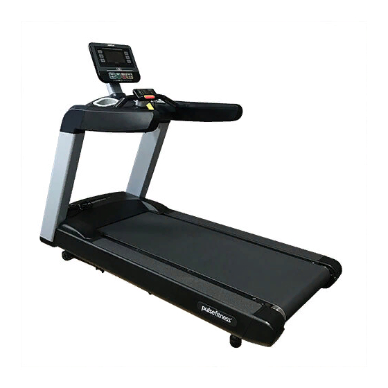
260G Overview 260G Run Console (Series 1, 2 or 3) ‘Quick’ Controls Emergency Stop Handpulse Resistors Treadplates Running Belt Book Rest iPod / iPhone Dock ® ® Drinks Bottle Storage Bucket Handrails Front Upright Supports Transportation Wheels Roller End Cap Assembly, Operation &... -
Page 8: Contents Of 260G Flat Pack
Contents of the 260G Pack The 260G Run will have to be assembled from the flat pack. The contents of the pack are as follows: Main Body Top Assembly Front Column Endcaps Upright Columns Storage Buckets Console (Series 1, 2 or 3) -
Page 9: Connecting The Support Columns
Assembly of 260G 3.1 Connecting the Support Columns Attach the support columns by placing the column against the front brackets and insert the bolts with washers into position whilst making sure you support the column. [See Figure A]. Note: Loosely tighten the bolts to, allowing 5mm of adjustment for connecting the top assembly. -
Page 10: Attaching The Column End Caps
Assembly of the 260G (Continued) 3.2 Attaching the Column End Caps Push the end cap into the column and insert the bolt through the hole, tightening with your fingers and then finishing off with an allen key. [See Figure B]. This procedure can be left to the end of the assembly once the side columns have been tightened into position. -
Page 11: Attaching The Top Assembly
Assembly of the 260G (Continued) 3.3 Attaching the Top Assembly Figure C Attaching the Top Assembly Attach the top assembly by dropping it onto the front columns, lifting the handrails and tilting the front brackets down into the front columns. Make sure that the holes are lined up in order to get the bolts into position. -
Page 12: Attaching The Neck
Assembly of the 260G (Continued) Figure D 3.4 Attaching the Neck Attaching the Neck Drop the neck through the hole in the dashboard moulding and secure with bolts. [See Figure D]. Tools Required: 13mm Combination Spanner [M8x75 Hexagon Head Bolt x2] Assembly, Operation &... -
Page 13: Attaching The Dashboard Valance
Assembly of the 260G (Continued) Figure E 3.5 Attaching the Dashboard Valance Attaching the Dashboard Valance Slide the dashboard valance into position and securely fix [See Figure E]. Note: Be careful not to damage the foam handrails during this process. -
Page 14: Fitting The Storage Buckets
Assembly of the 260G (Continued) Figure F 3.6 Fitting the Storage Buckets Fixing the Storage Buckets Insert the Storage buckets into the appropriate holes in the dashboard and press down firmly. [See Figure F]. Assembly, Operation & Parts Manual G-Range... -
Page 15: Fixing The Motor Cover
Assembly of the 260G (Continued) Figure G 3.7 Fixing the Motor Cover Fixing the Motor Cover Carefully slide the motor cover between the two uprights and drop into position [See Figure G]. Note: Make sure you do not scratch the front uprights during this process. -
Page 16: Installing Console
Installing Consoles on the 260G Figure H 4.1 Attaching / Re-Attaching the Console Attaching / Re-Attaching the Console For details on how to attach Series 1, 2 & 3 Consoles, refer to document 135-771-*. NOTE: Fasten Bolts securely. Tools Required:... -
Page 17: Wiring / Re-Wiring The Console
Installing Consoles on the 260G (Continued) Figure I 4.2 Wiring / Re-Wiring the Console Wiring / Re-Wiring the Console For details on how to connect the cables for Series 1, 2 & 3 Consoles, refer to document 135-799-*. Carefully pull the Electrical Connectors up from the Column. -
Page 18: Using The Console
Installing Consoles on the 260G (Continued) Figure J 4.3 Using the Console Using the Console For details on how to use each of the Series 1, 2 & 3 Consoles, refer to documents: 135-1379-* Series 1 (Console 3.5 CV) 135-1299-* Series 2 (Console 5.0 CV) 135-1300-* Series 3 (Console 6.0 CV) Cirrus V1... -
Page 19: Fully Assembled 260G Run
Fully Assembled 260G Run Your 260G Treadmill is now ready to use, please read the Technical and Console booklets to become familiar with all operational and safety features before use. Caution: MAKE SURE ALL HARDWARE IS TIGHT! Assembly, Operation & Parts Manual... -
Page 20: Quick Control Panel
* Standard settings setup. These are the Clear instruction needs to be given in order to use these controls. It is the recommended settings by PULSE FITNESS. It is the responsibility of the instructor/site to make sure that Users are aware of the function... -
Page 21: Connections To Power Supply
Connections to Power Supply 7.1 Wiring the Motor Note : 100-276-* Interface P.C.B. EARTH CABLE FILTER Sleeve Colour : N/A Cable supplied w/drive CAUTION MAINS POWER 120V P13 TO FILTER SPADES CABLE Cable supplied w/motor Sleeve Colour : N/A Ensure that the power is turned off and is Cable supplied w/actuator unplugged at the mains connection point, 12V PSU... -
Page 22: Important Safety Instructions
To disconnect, turn power OFF at the ON/OFF switch, then remove plug from electrical outlet. Never operate a PULSE FITNESS product if it has a damaged power cord or electrical plug, or if it has been dropped, damaged, or even partially immersed in water. Contact PULSE FITNESS' Global Service Team. - Page 23 Do not use this product outdoors, near swimming pools or in areas of high humidity. NEVER operate the PULSE FITNESS Run Treadmill with the Motor Panel removed. Never operate a PULSE FITNESS product with the air openings blocked. Keep air openings free of lint, hair, or any other obstructing material.
- Page 24 If warnings are missing or damaged, please contact PULSE FITNESS immediately for replacement warning labels. Warning labels are shipped with every product and should be installed before product is used. PULSE FITNESS is not responsible for missing or damaged warning labels.
-
Page 25: Set-Up
Important Safety Instructions (Continued) 8.2 Set-Up Read the entire manual before setting up the PULSE FITNESS Run (Low Impact 'Elevation' Treadmill). Place the Treadmill where it will be used before beginning the setup procedure. 8.3 Operation Always follow the Console instructions for proper operation. -
Page 26: Electrical Power Requirements
8.4 Electrical Power Requirements The PULSE FITNESS Run Treadmill requires a dedicated* electrical connection with an isolated neutral. * Commercial Units Only: One individual branch circuit for each treadmill is required per NEC article 210-21 (b) (1) and 210-23 (or other appropriate, country specific electrical compliance guidelines). -
Page 27: Safety Clearances
Important Safety Instructions (Continued) Figure L 8.6 Safety Clearances US Safety Clearances The following information is supplied as regional reference data regarding safety clearances around the exterior of the Treadmill. EU: The European EN957 Safety Standard requires 0.5m / 0.5m / a 2m (6.5ft) minimum from the rear of the treadmill 1.64ft 1.64ft... -
Page 28: Power Switch
Note: To accommodate Treadmill incline, at least 61cm / 24” of power cord is required between the outlet and the front of the Treadmill. WARNING: Make sure that there is a 2m / 6.5ft clearance behind the Treadmill. Contact PULSE FITNESS Global Service Team for a longer power cord (if necessary). -
Page 29: General Safety Precautions
9.1 Grounding Instructions This PULSE FITNESS product must be properly grounded. If the unit malfunctions or breaks down, proper grounding provides a path of least resistance for the electric current, which reduces the risk of shock to anyone touching or using the equipment. Each unit is equipped with an electrical cord, which includes an equipment grounding conductor and a grounding plug. -
Page 30: Emergency Stop
General Safety Precautions (Continued) 9.2 Emergency Stop The Treadmill is equipped with two different stop functions, which work as follows: Stop Function What the User does What the Treadmill Belt does What the Console does Shows that the exercise is paused. -
Page 31: Emergency Stop Safety Clip
General Safety Precautions (Continued) Figure N Figure O 9.3 Emergency Stop Safety Clip Incorrect Emergency Stop Correct Emergency Stop Safety Clip Procedure Safety Clip Procedure When operating the Treadmill the User must ALWAYS wear the Emergency Stop Safety Clip. If for whatever reason the Cord is pulled;... -
Page 32: Using The Emergency Stop Safety Clip
General Safety Precautions (Continued) Figure P 9.4 Using the Emergency Stop Safety Clip Attaching the Emergency Stop Safety Clip Users must ALWAYS use the Emergency Stop Safety Clip while exercising on the Treadmill. The Emergency Stop Safety Clip must be correctly attached to the User [see Figure O](page 31). -
Page 33: Speed Confirm. Quick Controls (C5.0)
Treadmill's speed quickly, the User has three safe methods available to stop the Treadmill: 1. Use (6.1) 260G 'Quick' Controls buttons (see page 20) 2. Use (9.3 & 9.4) Emergency Stop Magnet/Safety Clip (see pages 31 & 32) 3. -
Page 34: Speed Confirm. Quick Controls (C6.0)
User has three safe methods available to stop the Treadmill: Level Energy Power Time Distance Speed Calories 1. Use (6.1) 260G 'Quick' Controls buttons (see 30:00 0.00 page 20) 2. Use (9.3 & 9.4) Emergency Stop Magnet/Safety Mets watts kcals 23JUL 23JUL Clip (see pages 31 &... -
Page 35: Emergency Dismount
General Safety Precautions (Continued) Figure S 9.7 Emergency Dismount Emergency Dismount Never mount or dismount the Treadmill while the Running Belt is moving. Use the Handrails whenever additional stability is required. In case of an emergency, such as tripping, grasp the Handrails, and place the feet on the Treadplates [See Figure In any event where the User feels unable to keep... -
Page 36: Installation
Installation 10.1 Location Select a suitable location for the PULSE FITNESS Run Treadmill before moving it. The site you choose should meet the following requirements: A flat, level and clean surface. Ÿ Close to a suitable power socket. Ÿ Well away from sources of water (or other liquids) or away from areas that are subject to condensation. -
Page 37: Feet Adjustment
Installation (Continued) Figure U 10.2 Feet Adjustment Feet Adjustment WARNING Once the Treadmill has been sited you must ensure that it is stable. If there is even a slight rocking motion or the unit is not stable, determine which When installing or adjusting any piece of PULSE foot is not resting on the floor. -
Page 38: On/Off Switch
Installation (Continued) Figure V 10.3 On/Off Switch ON/OFF On / Off Switch Switch The Treadmill is delivered with a power cable which has a moulded plug already fitted. Plug the Treadmill into a suitable mains socket and then switch on the power. Switch on the Treadmill via the on/off (I / O) switch mounted at the front of the machine. -
Page 39: Adjust And Tension The Running Belt
How to Adjust and Tension the Running Belt Figure W 11.1 Running Belt Alignment Running Belt Alignment Do not move the Treadmill, or place hands under the Treadmill while it is plugged into an electrical outlet! Once the Running Belt is aligned, the overall tension can be checked to make sure that it does not slip on its Rollers, this is explained in section 11.2 and 11.3. -
Page 40: Tracking (Centring) A Running Belt
Note: Do not exceed one full turn of the adjusting screws in either direction. If after one full turn the Running Belt does not track properly, contact Pulse Fitness Global Service Team. Do not over tighten the tensioning bolts while making belt adjustments. Over tightening of bolts may over stretch and damage the Running Belt or Roller. -
Page 41: Tensioning An Existing Running Belt
How to Adjust and Tension the Running Belt (Continued) 11.3 Tensioning an Existing Running Belt a. Press GO and operate the treadmill for five minutes at 5Kph / 3.1Mph. Note: DO NOT RUN OR WALK ON THE RUNNING BELT. b. Reduce the speed to 3.0Kph / 1.9Mph. Walk on the Treadmill. Tightly grip the Handrails and apply force with feet on the Running Belt near the Motor Cover against the moving Belt direction. -
Page 42: Cleaning & Maintenance
Cleaning & Maintenance 12.1 Preventive Maintenance Tips PULSE FITNESS products are backed by engineering excellence and the reliability of the Global Service Team. The Treadmill is one of the most rugged and trouble-free pieces of exercise equipment on the market today. -
Page 43: Compatible Cleaners
Cleaning & Maintenance (Continued) 12.3 Compatible Cleaners DO NOT use water based solutions (on the following): Clean the display console, all exterior surfaces and the frame with a mild, non- abrasive silicon based household cleaner. Apply via a soft micro fibre cloth. Apply the cleaner to the cloth before cleaning. DO NOT use ammonia or acid based cleaners. -
Page 44: How To Obtain Product Service
WARNING: Failure to carry out maintenance on the equipment as per this manual could result in serious injury and void your warranty. Please ensure all publications supplied with PULSE FITNESS equipment are read and understood. 12.5 How to Obtain Product Service 1. -
Page 45: Specifications
Specifications 13.1 - PULSE FITNESS Run (Low Impact 'Elevation' Treadmill) specifications: Designed use: Heavy/Commercial. Motor power: 3.0HP (5.0HP Peak). Drive: Rhymebus AC Motor. Power requirements: EU - 220-240V, 50Hz, 13A, 1500W. US - 110-120V, 60Hz, 15A. Mains powered: Series 1, 2 & 3. - Page 46 Specifications (Continued) Waxing system: Self-lubricating Running Belt. Running Belt (cm/"): 152cm / 59 -3/16" Length x 54cm / 21-1/4" Width (between belt centres). Front Handrail: Ergonomically shaped, neoprene grips. Side Handrails (cm/"): 65cm / 25-9/16" x 15.5cm / 6-1/16" Long, flared, cantilevered, over-moulded grips. Workout pause with auto-reset: Series 2 &...
-
Page 47: Physical Dimensions (L X H X W)
Specifications (Continued) 13.2 Physical Dimensions (L x H x W) Length (cm/"): 214mm / 84-1/4" Height (cm/") 0% elevation: Series 1 & 2 = 160cm / 63", Series 3 = 163cm / 64-3/16" Height (cm/") 15% elevation: Series 1 & 2 = 196cm / 77-3/16", Series 3 = 199cm / 78-3/8" Width (cm/"): 88cm / 34-5/8"... - Page 48 Specifications (Continued) Workout Programmes: Series 1 - Quick Start, Goals (Time; Distance; Calories), Marathon mode, Pacer (Time and speed; Time and distance; Speed and distance), Profile: X-country (easy, moderate, advanced), Aerobic (easy, moderate, advanced), Hill climb (easy, moderate, advanced), Intervals (easy, moderate, advanced), Random (easy, moderate, advanced), Rockport fitness test with V02 result, Variable cool down with manual override.
- Page 49 Specifications (Continued) programmable units (imperial/metric), User selectable/management programmable language. Series 3 - Profile display with level indicator, Track display with level indicator (pacer mode only), Time elapsed/remaining (depending on program), Distance elapsed/remaining (depending on program), Speed, Elevation, Calories used, Watts, Heart rate, METs, Extendable workout goal, User weight entry (automatic when used with PulseMove Professional), User selectable/management programmable units (imperial/metric), User selectable/management programmable language.
-
Page 50: Parts Lists & Exploded Diagrams
Parts Lists & Exploded Diagrams Parts Lists & Exploded Diagrams Details on both Parts Lists & Exploded Diagrams for Series 2 & 3 260G Treadmills, please refer to documents: 135-1094-03-* Exploded Dia. (Short Version) 135-1093-01-* Series 2 (Console 5.0 CV) 135-1093-02-* Series 3 (Console 6.0 CV) -
Page 51: User Notes
User Notes Assembly, Operation & Parts Manual G-Range... - Page 52 User Notes (Continued) Assembly, Operation & Parts Manual G-Range...
- Page 53 England, United Kingdom Tel: +44(0)1260 294600 Fax: +44(0)1260 299282 Email: global.service@pulsefitness.com © 2018 Pulse Fitness Ltd. All rights reserved. Pulse Fitness, is a registered trademark. Any use of these trademarks, without the express written consent of Pulse Fitness ® ® ®...
Need help?
Do you have a question about the 260G and is the answer not in the manual?
Questions and answers