
Subscribe to Our Youtube Channel
Summary of Contents for Elettro CF TIG 2015 DC-HF
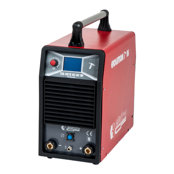
- Page 1 Elettro C.F. s.r.l. TIG 2015 DC-HF POWER SOURCE art. 168 SERVICE MANUAL 07/06/16...
-
Page 2: Table Of Contents
Elettro C.F. s.r.l. TABLE OF CONTENTS - GENERAL INFORMATION .......................... 3 - Introduction..............................3 - General assistance philosophy........................3 - Safety information............................. 3 - Electromagnetic compatibility........................3 - DESCRIPTION OF SYSTEM ........................4 - Introduction..............................4 - Technical specifications. -
Page 3: General Information
It is forbidden to try to repair damaged circuit boards or electronic modules. Replace them with original Elettro CF spare parts. 1.3 - Safety information. The following information regarding safety is an integral part of that provided in the Instruction Manual and the Safety Rules Manual. -
Page 4: Description Of System
Elettro C.F. s.r.l. 2 - DESCRIPTION OF SYSTEM 2.1 - Introduction. The TIG 2015 AC/DC-HF INVERTER is a system for MMA and TIG welding, with both contact and high frequency arc ignition. It consists of an electronic power source (art. 168), and a series of accessories to adapt it to different types of use. - Page 5 Elettro C.F. s.r.l. power board (14) which generates high-voltage pulses at high frequency for the transformer (33). The fan (7), for cooling the power elements of the power source, is controlled by the microprocessor of the power board (14). Its operation depends on the selected welding mode: If the machine is on in MMA mode or it switches to MMA mode, the fan is always on.
-
Page 6: Maintenance
Elettro C.F. s.r.l. 3 - MAINTENANCE WARNINGS ANY INTERNAL INSPECTION OR REPAIR MUST BE CARRIED OUT BY QUALIFIED PERSONNEL. BEFORE PERFORMING MAINTENANCE, DISCONNECT THE MACHINE FROM THE MAINS AND WAIT FOR THE INTERNAL CAPACITORS TO DISCHARGE (2 MINUTES) 3.1 - Periodical inspection, cleaning. Periodically check the correct air inflow inside the ventilation tunnel. -
Page 7: Switching On Power Source
Elettro C.F. s.r.l. NOTE Operations preceded by this symbol refer to actions of the operator. ♦ Operations preceded by this symbol refer to responses of the machine to the operation carried out by the operator. 3.2.2 - Switching on power source. System off and disconnected. -
Page 8: Tig Operation
Elettro C.F. s.r.l. 3.2.3 - TIG operation. NOTE The TIG-AC operating sequence is described below, because it involves all of the internal power source units, including those for TIG-DC operation. WARNINGS DURING THE FOLLOWING TESTS, DO NOT AIM THE TORCH TOWARDS PERSONS OR BODY PARTS BUT TOWARDS AN OPEN SPACE OR THE PIECE TO BE WELDED. -
Page 9: Mma Operation
Elettro C.F. s.r.l. Correct? NO (see 3.3.8, 3.3.9). Release the start button on the torch. ♦ The arc switches off immediately (if long slope-down times are not set). ♦ Gas continues to come out to protect the welding bath (post-gas). Correct? NO (see 3.3.5, 3.3.9). -
Page 10: Troubleshooting
Elettro C.F. s.r.l. 3.3 - Troubleshooting. WARNINGS ANY INTERNAL INSPECTION OR REPAIR MUST BE CARRIED OUT BY QUALIFIED PERSONNEL. DISCONNECT THE POWER SOURCE FROM THE MAINS AND WAIT FOR THE INTERNAL CAPACITORS TO DISCHARGE (2 MINUTES) BEFORE REMOVING THE PROTECTIVE COVERS AND ACCESSING THE INTERNAL PARTS. NOTE The problems which the machine could have (symptoms).are described in boldface. -
Page 11: Power Source Supplied, Fan (7) Stopped
Elettro C.F. s.r.l. ♦ Check wiring between J1 power board (14) and J2 panel board (18). ♦ With power source off, temporarily disconnect the connector J2 on panel board (18) and verify that the terminals 25 and 24 of J2 panel board (18) are not short- circuited. - Page 12 Elettro C.F. s.r.l. Power board (14), connector J7, terminals 6(+) and 8(-) = 0 Vdc (UP command), with UP button pressed (+5 Vdc with button released). Power board (14), connector J7, terminals 5(+) and 8(-) = 0 Vdc (DOWN command), with ...
-
Page 13: In Tig Mode, The Start Button Has No Effect
Elettro C.F. s.r.l. 3.3.4 - In TIG mode, the start button has no effect. START COMMAND TEST. Power board (14), connector J7, terminals 4(+) and 8(-) = 0 Vdc (start), with start button pressed (+5 Vdc with button released). Correct? ♦... -
Page 14: In Tig Mode, Gas Comes Out The Torch But Does Not Ignite The Arc, High Frequency Missing
Elettro C.F. s.r.l. 3.3.6 - In TIG mode, gas comes out the torch but does not ignite the arc, high frequency missing. WARNING DURING THE FOLLOWING TESTS, LEAVE THE NEGATIVE OUTPUT TERMINAL (F) OF THE POWER SOURCE FREE FROM CONNECTIONS AND DO NOT TOUCH. THE PRESENCE OF HIGH VOLTAGE AND HIGH FREQUENCY IS DANGEROUS FOR THE OPERATOR AND COULD DAMAGE THE INSTRUMENTS OR THE POWER SOURCE... -
Page 15: In No-Load Operation, The Output Voltage Is Not Regular
Elettro C.F. s.r.l. 3.3.7 - In no-load operation, the output voltage is not regular. WARNING FOR THE FOLLOWING TESTS, DISCONNECT THE TERMINALS OF THE PRIMARY WINDING OF THE HF TRANSFORMER (33) FROM TERMINALS J22, J23 OF POWER BOARD (14), TO PREVENT GENERATION OF HIGH FREQUENCY NO-LOAD OUTPUT VOLTAGE TEST. -
Page 16: In Resistive Load Operation, The Output Voltage Is Not Regular
Elettro C.F. s.r.l. POWER RESISTOR (6) TEST AC-board (38), resistor connection CN8= 15 Ω approx.; Correct? ♦ Replace resistors (6). ♦ Regular operation. AC-BOARD (38) ENABLE TEST. AC-board (38), connector CN1, terminals 2(+) and 4(-) = +5 Vdc approximately, in TIG-DC ... -
Page 17: In Tig Mode, Arc Unstable, Welding Irregular
Elettro C.F. s.r.l. Process Resistive load Maximum output Power source Condition resistance current output voltage TIG-DC 0.090 ohm 200 A + 18 Vdc Start button pressed TIG-AC 0.090 ohm 200 A 18 Vac Start button pressed 0.165 ohm 160 A + 26.4 Vdc Power source powered OUTPUT VOLTAGE ON RESISTIVE LOAD TEST. -
Page 18: Error Codes
Elettro C.F. s.r.l. out welding tests in DC and, if necessary, the “open circuit operation” test (par. 3.3.7) and “operation on resistive load” test (par. 3.3.8). 3.4 - Error codes. 3.4.1 - Symbol on display. Temperature exceeded limit alarm. The thermostat is placed on the power IGBT heat sink of the power board (14). The power source does not provide current, but the fan keeps running;... -
Page 19: List Of Components
Elettro C.F. s.r.l. 4 - LIST OF COMPONENTS 4.1 - POWER SOURCE art. 168: see diagram on page 26 4.2 – Components table: see table on page 24 4.3 – Spare parts list. Essential spare parts. Ref. Description Q.ty display board connector board power board AC-board... -
Page 20: Wiring Diagrams
Elettro C.F. s.r.l. 5 - WIRING DIAGRAMS 5.1 - Power source art. 168: see diagram on page 26 5.2 - Power board (14) 5.2.1 - Topographic drawing. 07/06/16... -
Page 21: Display Board (18)
Elettro C.F. s.r.l. 5.2.2 - Connectors table. Conn. Terminals Function solenoid valve (23) 230 Vac power supply output. fan (7) 230 Vac power supply output. output“–“ for torch potentiometer “DOWN” signal input. “START” signal input. “common” output for signals from/through connector board (28). torch potentiometer cursor input. -
Page 22: Connector Board (28)
Elettro C.F. s.r.l. 5.4 - Connector board (28) 5.4.1 - Topographic drawing. 5.4.2 - Connectors table. Conn. Terminals Function “common” input for external signals. torch potentiometer cursor output. “START” signal output. “UP” signal output. “DOWN” signal output. input “-“ for torch potentiometer. +14.5V input from power circuit (14) power source output voltage reading signal output, for power circuit (14). -
Page 23: Ac-Board (38)
Elettro C.F. s.r.l. 5.5 – AC-board (38) 5.5.1 - Topographical drawing. 5.5.2 - Connectors table. Connector Terminals Function 1 - 2 - 3 - 4 input to enable AC board (38). 1 - 2 27 Vac input for AC board (38). 1 - 2 260 Vac input. - Page 24 Elettro C.F. s.r.l. POS. DESCRIZIONE DESCRIPTION BESCHREIBUNG DESCRIPTION DENOMINACIÓN DESCRIÇÃO OMSCHRIJVING SOPORTE SUPPORTO MANICO HANDLE SUPPORT GRIFFHALTERUNG SUPPORT POIGNEE SUPORTE CABO HANDVATHOUDER EMPUÑADURA MANICO HANDLE GRIFF POIGNEE EMPUÑADURA CABO HANDVAT MANOPOLA KNOB REGLER BOUTON MANECILLA MANÍPULO KNOP TEXAS ACOPLAMIENTO INNESTO TEXAS TEXAS-KUPPLUNG CONNEXION TEXAS CONECTOR TEXAS...
- Page 25 Elettro C.F. s.r.l. La richiesta di pezzi di ricambio deve indicare sempre: l' art. e la data d'acquisto della macchina, la posizione e la quantità dei pezzi di ricambio. In case spare parts are required please always indicate: item ref. no. and purchase date of the machine, spare part position no. and quantity. Bei der Ersatzteilanfrage müssen immer Art.
- Page 26 Elettro C.F. s.r.l. 07/09/20...
- Page 27 Elettro C.F. s.r.l. Farben-Codierung Codification Codificación Codificação cores Codifica colori Wiring diagram elektrische couleurs schéma colores cableado conjunto eléctrico cablaggio elettrico colour code Schaltplan électrique eléctrico de cabos Nero Black Schwarz Noir Negro Negro Rosso Rouge Rojo Vermelho Grigio Grey Grau Gris Gris...
- Page 28 Elettro C.F. s.r.l. 07/09/20...
Need help?
Do you have a question about the TIG 2015 DC-HF and is the answer not in the manual?
Questions and answers