
Summary of Contents for EaseTech ACCURON 7200 Series
- Page 1 ACCURON ® 7200 CARTRIDGE METERS INSTALLATION & OPERATING MANUAL eastech FLOW CONTROLS 4250 S. 76th E. Ave. Tulsa, OK 74145 918-664-1212 800-226-3569 Fax: 918-664-8494 email: info@eastechflow.com eastech...
- Page 2 ACCURON CARTRIDGE METER SERIES 7200 INSTALLATION & OPERATING MANUAL SCOPE OF MANUAL This manual contains information concerning the installation, operation and maintenance of the Accuron 7200 Cartridge Meter. To ensure proper performance of the meter, the instructions given in this manual should be thoroughly understood and followed.
- Page 3 ACCURON CARTRIDGE METER SERIES 7200 INSTALLATION & OPERATING MANUAL UNPACKING & INSPECTION Retain the container and all packing material for possible use in reshipment or storage. Visually inspect the product and applicable accessories for any physical damage such as scratches, loose or broken parts, or any other sign of damage that may have occurred during shipment.
-
Page 4: Table Of Contents
ACCURON CARTRIDGE METER SERIES 7200 INSTALLATION & OPERATING MANUAL TABLE OF CONTENTS TABLE OF CONTENTS General Description ..... . . 2, 3 Daily Totals . -
Page 5: General Description
ACCURON CARTRIDGE METER SERIES 7200 INSTALLATION & OPERATING MANUAL GENERAL DESCRIPTION LOW FLOW MONITORING Accuracy ±3-5% (act.rate) Turndown: 60:1 During periods The Series 7200 Cartridge Meter is designed to measure of minimal flow (Zero to 1/3 flow in open channels or partially filled conduits. The pipe diameter), the Accuron Cartridge Meter utilizes ultrasonic measurments measures flow within it’s low... -
Page 6: General Specifications
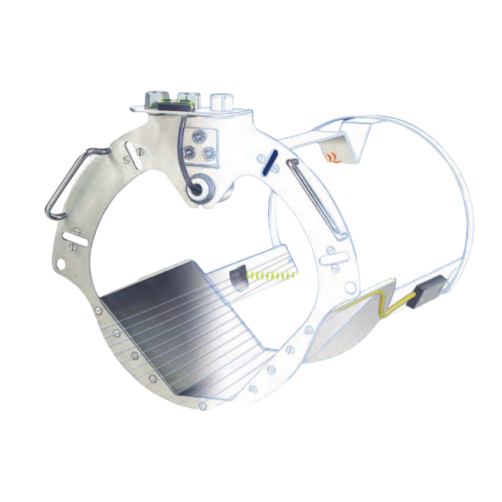
ACCURON CARTRIDGE METER SERIES 7200 INSTALLATION & OPERATING MANUAL GENERAL SPECIFICATIONS Pipe Size Range 8 “ to 24” Output: Three 4-20mADC isolated; 850 ohms max.Flow, Level and Velocity Three programmable relays, SPDT .25 amp @ 120 VAC, .5 amp @ 24 VDC RS-232 Serial Port, 9600 –... - Page 7 ACCURON CARTRIDGE METER SERIES 7200 INSTALLATION & OPERATING MANUAL FIELD READY INSTALLATION THE CARTRIDGE METER IS A SINGLE FACTORY INTEGRATED UNIT, DESIGNED FOR 30 MINUTE FIELD INSTALLATION AND VALIDATION. PRE-SIZED Each field ready cartridge is pre-sized for it’s intended application. Gasketed and manufactured of 304 stainless steel, cartridges are installed within minutes.
- Page 8 ACCURON CARTRIDGE METER SERIES 7200 INSTALLATION & OPERATING MANUAL CARTRIDGE INSTALLATION HARDWARE (Supplied by Eastech) Masonry drill bit (1) Lag shields (4) Lag bolts (4) Turnbuckles (2) Socket Drill Bit (1) Flat washes (10) Marker (1)
- Page 9 ACCURON CARTRIDGE METER SERIES 7200 INSTALLATION & OPERATING MANUAL STEP 1 STEP 2 The Cartridge should be installed in the Slide the Cartridge into the pipe until the incoming pipe of the manhole. upstream flange is in contact with the wall.
- Page 10 ACCURON CARTRIDGE METER SERIES 7200 INSTALLATION & OPERATING MANUAL STEP 3 STEP 4 Rotate the Cartridge until the bubble in level Use a pencil or marker and mark the four provided is centered. slotted holes provided in the flange of the Cartridge.
- Page 11 ACCURON CARTRIDGE METER SERIES 7200 INSTALLATION & OPERATING MANUAL STEP 5 STEP 6 Using the drill and the masonry drill bit Insert the lag shields flush to the wall. provided, drill all four holes for the lag shield.
- Page 12 ACCURON CARTRIDGE METER SERIES 7200 INSTALLATION & OPERATING MANUAL STEP 7 STEP 8 If installing the Cartridge in a round manhole, Re-insert the Cartridge. Line up the slots it may be necessary to use flat washers as with the lag shield holes and screw the lag spacers between the Cartridge flange and bolts with the flat washers through the the wall.
-
Page 13: Enclosure Mounting
ACCURON CARTRIDGE METER SERIES 7200 INSTALLATION & OPERATING MANUAL ENCLOSURE MOUNTING Hinge Lock and Optional Key Lock 8.25” 9.32” 12.625” 8.875” 13.25” Do not face the display towards the sun. A sunshade must be used for outdoor installation. Conduit openings must be properly prepared and sealed to maintain the NEMA 4X rating. -
Page 14: Sensor Cable Preparation
ACCURON CARTRIDGE METER SERIES 7200 INSTALLATION & OPERATING MANUAL SENSOR CABLE PREPARATION VELOCITY SENSORS (PAIR) 2. Remove outer shield. Measure 1-3/8” from the end of the cable. With a pair of small side cutters, cut the shield IMPORTANT around the cable at the measured point and remove the Before pulling the sensor cables through the conduits, outer shield. - Page 15 ACCURON CARTRIDGE METER SERIES 7200 INSTALLATION & OPERATING MANUAL 3. Remove middle cover. Measure 1-1/8” from the end of 4. Remove middle shield. Measure 3/4” from the end of the cable. With a cutting tool, carefully cut through the the cable. With a pair of small side cutters, cut the shield middle cover making sure not to cut into the middle around the cable and remove middle shield.
- Page 16 ACCURON CARTRIDGE METER SERIES 7200 INSTALLATION & OPERATING MANUAL 5. Remove inner cover. Measure 1/2” from the end of the USE DRAWING BELOW AS TEMPLATE cable. With a cutting tool or pair of wire strippers, FOR CONFIRMATION carefully cut the inner covering, making sure not to cut OF CORRECT CABLE PREPARATION into the center conductor.
-
Page 17: Level Sensor
ACCURON CARTRIDGE METER SERIES 7200 INSTALLATION & OPERATING MANUAL LEVEL SENSOR CABLE PREPARATION SINGLE LEVEL SENSOR WHITE VELOCITY & LEVEL SENSOR WIRING BLACK, GREEN, SHIELD Red Wire: Strip wire approximately 1/4 to 3/8” White Wire: Strip wire approximately 1/4 to 3/8” Black, Green and Shield Wires: Strip black and green wire and crimp all three wires into the spade lug provided. - Page 18 ACCURON CARTRIDGE METER SERIES 7200 INSTALLATION & OPERATING MANUAL METER ENCLOSURE WIRING METER WIRING DIAGRAM There are three terminal strips provided for all wiring of the Accuron 7200. the AC power terminal is separate from the other two terminal strips. The power terminal strip has three connections for High (Hot), Low (Neutral), and Ground for AC voltage only.
- Page 19 ACCURON CARTRIDGE METER SERIES 7200 INSTALLATION & OPERATING MANUAL METER WIRING cont. VELOCITY SENSOR CABLE CONNECTIONS After the ends of the cables have been prepaired, loosen the screws on the terminals and remove the two pairs of OUTPUTS clamps on the velocity sensor cable terminal board. CHANNEL 1 3) 4-20 mADC Isolated into 850 ohms max...
- Page 20 ACCURON CARTRIDGE METER SERIES 7200 INSTALLATION & OPERATING MANUAL VELOCITY SENSOR LEVEL SENSOR CABLE CONNECTIONS PROPER INSTALLATION CONFIRMATION Sensor cable connection continuity test. WHITE LEVEL Black, Green & Shield This test will require the use of an ohmmeter. With the SENSOR power off, connect the test leads of the ohmmeter to Points 1 and 3 of the sensor cable connections on the...
-
Page 21: Programming
ACCURON CARTRIDGE METER SERIES 7200 INSTALLATION & OPERATING MANUAL PROGRAMMING Programming of the sensor parameters for the ENTER AND ADJUSTMENT KEYS Cartridge Meter is not necessary. Since each unit is NUMERIC PROGRAMMING KEYS pre-sized for it’s intended application, and the velocity and level sensors are precision factory 5 FUNCTION KEYS aligned prior to shipment, the only field... - Page 22 ACCURON CARTRIDGE METER SERIES 7200 INSTALLATION & OPERATING MANUAL Power-up Screen Main Screen On power up, the display will indicate for a few seconds The Accuron 7200 main screen displays flow, velocity the current revision and check/sum (used to validate the and totals.
- Page 23 ACCURON CARTRIDGE METER SERIES 7200 INSTALLATION & OPERATING MANUAL F1-1 F1-2 F1-1 displays phase shift in degrees, transit time in F1-2 displays the status and gain required by each milliseconds, velocity in feet per second, the measured channel to maximize the signal strength (a lower distance from the level sensor to the fluid, and the number indicates a strong signal).
- Page 24 ACCURON CARTRIDGE METER SERIES 7200 INSTALLATION & OPERATING MANUAL F1-3 F1-3 displays the status of the alarms based on set Two pages of details can be accessed from the F2 key; points, the 4-20mA loop and assigned relays (see F2-1and F2-2 OPTIOINS for assigning set points).
- Page 25 ACCURON CARTRIDGE METER SERIES 7200 INSTALLATION & OPERATING MANUAL F3 displays forward and reverse (reverse velocity) totals F4 displays the eight available channels and the from the last 8 days. Starting with day 0 (current day) currently selected parameters (see OPTIONS for pressing the left and right arrow keys will cycle through choosing other parameter settings).
- Page 26 ACCURON CARTRIDGE METER SERIES 7200 INSTALLATION & OPERATING MANUAL F5 displays firmware revision and check/sum. The X range can be adjusted by pressing the left and right arrow keys. The Y scale can be altered with the F2 and or F3 key. F2 will adjust the range and F3 will adjust the offset.
- Page 27 ACCURON CARTRIDGE METER SERIES 7200 INSTALLATION & OPERATING MANUAL OPTIONS Below is a quick overview of the menu system. >01) Review Meter (ENTER) Displays the sensor mounting and programmed parameters. Programming Overview >02) Program 01) Measure Units Assign units of flow, velocity, temperature and distance. 02) Level (H) Sensor To set sensor frequency, distance and temperature Although all of the necessary parameters have been calibration.
-
Page 28: Programming Options
ACCURON CARTRIDGE METER SERIES 7200 INSTALLATION & OPERATING MANUAL PROGRAMMING >01) Review Meter OPTIONS 01-1 and 01-2 display sensor set-up details programmed at the factory. These details are provided for reference only. Press ENTER to cycle through the status pages and return to the MAIN MENU. -
Page 29: Program
ACCURON CARTRIDGE METER SERIES 7200 INSTALLATION & OPERATING MANUAL >02) Program >02) Program Programming parameters are password protected in 01) Measure Units: order to prevent accidental or malicious changes. Initially From the main screen press the MENU key then the number the password is factory set to 00000000. - Page 30 ACCURON CARTRIDGE METER SERIES 7200 INSTALLATION & OPERATING MANUAL Flow Display format: The FLOW DISPLAY FORMAT screen allows selection of the number of digits displayed to the right of the decimal point. Dimension Units: Example: GPM, #.## would Five options are presented for display 100 gallons per minute the DIMENSION UNITS: 01) as 100.00 GPM.
-
Page 31: Level (H) Sensor Set-Up
02). reference. Enter the actual temperature as measured by an 01) Distance Calibration: external device. The Accuron 7200 series meters Press MENU and ENTER to store are pre-calibrated as a unit at the changes. factory. There may be situations... -
Page 32: Totalizer
ACCURON CARTRIDGE METER SERIES 7200 INSTALLATION & OPERATING MANUAL >02) Program >02) Program 04) 4-20 Outputs 03) Totalizer: From the main screen, press the From the main screen, press the MENU key then the number MENU key then the number 02. 02. -
Page 33: Damping
ACCURON CARTRIDGE METER SERIES 7200 INSTALLATION & OPERATING MANUAL >02) Program >02) Program Application Full Scale: 05) Damping: Enter the Full Scale values for level, From the main screen, press the velocity and flow. MENU key then the number 02. Enter the password (default is Press ENTER to advance to 00000000) and press the ENTER key... -
Page 34: Flow Simulation
ACCURON CARTRIDGE METER SERIES 7200 INSTALLATION & OPERATING MANUAL >02) Program >02) Program 07) Flow Simulation: 09) Set points: Press MENU, 02, Password, Press MENU, 02, Password, ENTER and 07. ENTER and 09. The Flow Simulator allows Three set points are available the user to enter an arbitrary to outline flow conditions level and velocity to observe... -
Page 35: Relays
ACCURON CARTRIDGE METER SERIES 7200 INSTALLATION & OPERATING MANUAL >02) Program >03) Daily Totals 10) Relays: Daily Totals: Press MENU, 02, Password, Press MENU followed by 03. ENTER and 10. Displays forward and reverse The Accuron 7200 has three (reverse velocity) totals from the assignable relays. -
Page 36: Data Logger
ACCURON CARTRIDGE METER SERIES 7200 INSTALLATION & OPERATING MANUAL >04 Data Logger >04 Data Logger The data logger is the fourth branch of the main menu. 01) Set Time: Press MENU, 04, Password, It provides access to eight critical functions of the 7200’s ENTER and 01. -
Page 37: Secondary Storage
ACCURON CARTRIDGE METER SERIES 7200 INSTALLATION & OPERATING MANUAL >04 Data Logger >04 Data Logger 03) Secondary: 05) Logged Graph: Press MENU, 04, Password, Press MENU, 04, Password, ENTER and 03. ENTER and 05. Data can be stored at different The Logged Graph displays rates. -
Page 38: Logged Data
ACCURON CARTRIDGE METER SERIES 7200 INSTALLATION & OPERATING MANUAL >04 Data Logger >05 System Set-up 06) Logged Data System Set-up provides admittance to nine system Press MENU, 04, Password, configuration sub-menus. The set-up functions are ENTER and 06. password protected due to the systems dependence on The Logged Data displays the these settings. -
Page 39: Display
ACCURON CARTRIDGE METER SERIES 7200 INSTALLATION & OPERATING MANUAL >05 System Set-up >05 System Set-up 01) Display: RS-232/485 Comm Port: There are three parameters that must be Press MENU, 05, Password, set correctly before a communication ENTER and 01. link can be made (four if a modem is To improve screen visibility, used). -
Page 40: Daily Total Reset
ACCURON CARTRIDGE METER SERIES 7200 INSTALLATION & OPERATING MANUAL >05 System Setup >05 System Setup 06) Daily Tot Reset: 08) Meter Reset: Press MENU, 05, Password, Press MENU, 05, Password, ENTER and 06. ENTER and 08. Daily totals can be reset. To Entering 08) resets the meter to prevent an accidental reset, it original settings. -
Page 41: Factory Assistance
ACCURON CARTRIDGE METER SERIES 7200 Factory Assistance For Technical Assistance, please call Eastech at 1-800-226-3569 and ask for either Mark LaPlante or Craig Stewart.
Need help?
Do you have a question about the ACCURON 7200 Series and is the answer not in the manual?
Questions and answers