Table of Contents
Advertisement
Available languages
Available languages
Quick Links
A
l
i
m
e
n
t
a
A
l
i
m
e
n
t
a
A
l
i
m
e
n
t
a
N
N
Notice de Fonction ement
Copyright ©
AX 1360P
t
i
o
n
P
r
o
t
i
o
n
P
r
o
t
i
o
n
P
r
o
D
D
D
M
u
M
M
P
r
o
g
r
a
P
r
o
g
r
a
P
r
o
g
r
a
P
o
P
o
P
o
o
t
i
c
e d
e F
o
n
c
t
i
o
n
o
t
i
c
e d
e F
o
n
c
t
i
o
n
U
s
e
r
'
s
M
a
n
u
U
s
e
r
'
s
M
a
n
u
User's Manual
g
r
a
m
m
a
g
r
a
m
m
a
g
r
a
m
m
a
C
M
u
l
t
i
v
C
M
u
l
t
i
v
C
M
u
l
t
i
v
l
t
i
-
c
h
a
n
u
l
t
i
-
c
h
a
n
u
l
t
i
-
c
h
a
n
m
m
a
b
l
e
m
m
a
b
l
e
m
m
a
b
l
e
w
e
r
S
u
p
w
e
r
S
u
p
w
e
r
S
u
p
n
e
m
e
n
t
n
e
m
e
n
t
n
a
l
a
l
X03741A00 - Ed. 01 - 09/11
b
l
e
b
l
e
b
l
e
o
i
e
o
i
e
o
i
e
n
e
l
n
e
l
n
e
l
D
C
D
C
D
C
p
l
y
p
l
y
p
l
y
Advertisement
Chapters
Table of Contents

Related Manuals for Metrix AX 1360P

Summary of Contents for Metrix AX 1360P
- Page 1 AX 1360P Notice de Fonction ement ’ ’ User’s Manual X03741A00 - Ed. 01 - 09/11 Copyright ©...
- Page 3 AX 1360P Notice de Fonction ement .........3 ’ ’ User’s Manual............28 Alimentation programmable DC I - 1...
-
Page 4: Table Of Contents
Instructions générales FR - Sommaire Instructions générales Chapitre I Introduction ................... 3 Précautions d’emploi................3 Consignes de sécurité................3 Environnement opérationnel ............... 4 Garantie....................4 Maintenance, réparations, étalonnage ..........4 Nettoyage....................4 Remplacement des fusibles..............5 Description de l’instrument Chapitre II Introduction ................... -
Page 5: Introduction
Instructions générales Instructions générales Introduction Vous venez d'acquérir une AX 1360P Alimentation programmable DC multi- voie et nous vous remercions de votre confiance. Précautions Afin d'obtenir le meilleur service: - veuillez lire cette notice avec attention, d'emploi - respectez les consignes de sécurité. -
Page 6: Environnement Opérationnel
Instructions générales Instructions générales (suite) • Environnement Situation : intérieur, pas d’exposition directe au soleil, sans poussières, opérationnel pollution non-conductrice quasi nulle. • Humidité relative : < 80 % • Altitude : < 2000 m • Température : 0 à 40 ° C (Niveau de Pollution) CEI 61010-1 : définit les niveaux de pollution et leurs exigences. -
Page 7: Maintenance, Réparations, Étalonnage
Instructions générales Instructions générales (suite) Pour les réparations sous garantie et hors garantie, contactez votre agence Maintenance, commerciale CHAUVIN ARNOUX la plus proche ou votre centre technique réparations, régional Manumesure, qui établira un dossier de retour et vous étalonnage communiquera la procédure à suivre. Coordonnées disponibles sur notre site : http://www.chauvin-arnoux.com par téléphone aux n... -
Page 8: Introduction
Description de l'instrument Description de l'instrument L'alimentation DC programmable est légère, ajustable et multi- fonctions. Introduction L'appareil possède trois sorties indépendantes: • deux, ayant un niveau de tension ajustable • l'autre, une tension fixe, qui peut être sélectionnée entre : 2,5 V, 3,3 V et 5 V. -
Page 9: Caractéristiques Principales
Voltmètre Ampèremètre Interface USB 0 ~ 30 V x 2 0 ~ 3 A x 2 fixe AX 1360P LED 3 chiffres LED 3 chiffres 2,5 V / 3,3 V / 5 V • Performance Niveau bas d'ondulation et de bruit, ventilateur de refroidissement intelligent •... -
Page 10: Vue Générale De La Face Avant
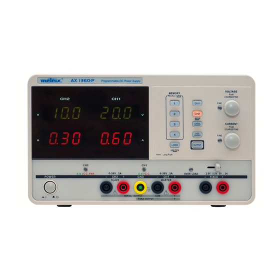
Description de l'instrument Description de l'instrument (suite) Vue générale de la face avant Touches Touches BEEP Mémoire Bouton Tension Voltmètre Touches Parallèle Série Ampèremètre Bouton Courant Touche Sortie Touche Verrouillage Bouton Sortie Indicateur de Borne de Sortie CH3 Sortie CH1 marche/arrêt - courant constant terre... -
Page 11: Face Avant
Description de l'instrument Description de l'instrument (suite) Face avant Touches mémoire Sauvegarde ou restaure les paramètres de la face avant. 4 jeux de paramètres max. prédéfinis. Voir page 20, pour les détails. Touches sonores CH1 CH2 Sélectionne la voie de sortie pour ajustement du niveau. -
Page 12: Bornes
Description de l'instrument Description de l'instrument (suite) Bornes Sous tension ou hors tension . Voir page 12, pour la Interrupteur alimentation mise sous tension. Accepte un câble de terre. Borne GND Sorties CH1 tension et courant. Sortie CH1 Indicateur Pour CH1 : indique le mode de fonctionnement tension constante ou courant constant CH1 CV/CC Sortie CH2... -
Page 13: Vue Générale De La Face Arrière
Description de l'instrument Description de l'instrument (suite) Vue générale de la Cordon face arrière d’alimentation Ventilation Connexion USB pour PC Porte-fusible Connexion USB Accepte un connecteur USB esclave pour la commande à distance via PC. Le cordon d'alimentation accepte l'alimentation Cordon d'alimentation secteur AC. -
Page 14: Mise Sous Tension
Configuration Configuration Ce chapitre décrit comment mettre l'alimentation sous tension avant son utilisation. Mise sous tension Branchez le cordon d'alimentation AC Branchement du cordon à la prise du panneau arrière. d'alimentation AC Appuyez sur l'interrupteur d'alimentation pour mettre sous tension. L'écran Mise sous tension d'initialisation contenant le nom du modèle suivi des derniers paramètres chargés s’affiche. -
Page 15: Sortie On/Off
Configuration Configuration (suite) Sortie ON/OFF Un appui sur la touche sortie active toutes les sorties Procédure CH 1 / 2 / 3. La touche LED est aussi activée. Un appui supplémentaire sur la touche sortie désactive les sorties et la touche LED. Sortie désactivée En cas de changement inattendu du niveau de sortie, une des actions automatiquement... -
Page 16: Mode Indépendant Ch1/Ch2
Fonctionnement Fonctionnement 1. Mode Indépendant CH1/CH2 Connexion Les sorties CH1 et CH2 fonctionnent indépendamment l'une de l'autre et sont contrôlées séparément. 0 ~ 30 V / 0 ~ 3 A par voie. Puissance de sortie Procédure 1. Assurez-vous que les touches PARA INDEP et SERIES INDEP sont éteintes (les LED des touches sont éteintes). -
Page 17: Mode Indépendant Ch3
Fonctionnement Fonctionnement (suite) 2. Mode Indépendant La puissance de CH3 est de 2,5 V / 3,3 V / 5 V, maximum 3 A. Elle Connexion fonctionne indépendamment de CH1 et CH2, quelque soit leur mode. Puissance de Fixe 2,5 V / 3,3 V / 5 V, 3 A sortie CH3 ne possède pas de mode tracking série/parallèle. -
Page 18: Mode Série Tracking Ch1/Ch2
Fonctionnement Fonctionnement (suite) 3. Mode série Tracking CH1/CH2 Le fonctionnement en série tracking double la capacité de tension de la série alimentation en interne, en reliant CH1 (Master) et CH2 (esclave) en série et en combinant la sortie d'une seule voie. CH1 (Master) contrôle le niveau de tension de sortie combinée. -
Page 19: Tracking Série Avec Borme Commune
Fonctionnement Fonctionnement (suite) 5. Pour activer la sortie, appuyez sur la touche sortie. La LED de la touche est activée. 6. Consultez le compteur CH1 (Maître) et l'indicateur pour le niveau de paramétrage de sortie et le statut CV/CC. Niveau de tension Doublez la mesure du Voltmètre CH1. - Page 20 Fonctionnement Fonctionnement (suite) 4. Appuyez sur l'interrupteur CH1 (la LED s'allume) et utilisez le commutateur tension pour ajuster la tension de sortie maître et esclave (même niveau pour les deux voies). Par défaut, les boutons Tension et Courant sont en mode large. Pour activer le mode fin, appuyez sur le commutateur et activez la LED FINE.
-
Page 21: Mode Tracking Parallèle Ch1/Ch2
Fonctionnement Fonctionnement (suite) 4. Mode Tracking Parallèle CH1/CH2 Connexion Le fonctionnement en tracking parallèle double la capacité de courant de l'alimentation en connectant CH1 et CH2 en parallèle en interne et en combinant la sortie sur une seule voie. CH1 contrôle la sortie combinée. Puissance de sortie 0 - 30 V / 0 - 6 A Procédure... -
Page 22: Sauvegarder La Configuration
Sauvegarde / Restauration Sauvegarde / Restauration Sauvegarder la configuration Introduction La configuration de réglage des paramètres de face avant peut être stockée dans une des quatre mémoires internes. Programmation La liste suivante donne la liste des paramètres sauvegardés: Mode Indépendant / tracking série / tracking parallèle Sélection de CH1/CH2 par le commutateur Mode commutateur gros/fin Alarme sonore ON/OFF... -
Page 23: Programmation À Distance
Programmation à distance Programmation à distance Programmation à distance Introduction Les paramètres de la face avant peuvent être restaurés à partir d'une des quatre mémoires internes. Interface port esclave USB, panneau arrière Paramètre COM Configurez le port COM du PC selon la liste suivante: Baud rate : 9600 Bit de parité... -
Page 24: Messages D'erreur
Programmation à distance Programmation à distance (suite) Messages d’erreur En cas d’erreur, les messages suivants peuvent apparaître : La commande ne doit pas dépasser 12 caractères. Program mnemonic too long Invalid character Un caractère invalide de type symbole a été entré. Exemple: VOUT# Too many digits La commande ne doit pas dépasser 3 digits. -
Page 25: Détail Des Commandes
Programmation à distance Programmation à distance (suite) Détail des commandes Commande ISET<X> Commande ISET<X>:<NR2> Description Retourne le réglage du Description Règle le courant de sortie courant de sortie. Mode de Voir p. 11. Temps de min. 70ms fonctionnement réponse Temps de min. - Page 26 Programmation à distance Programmation à distance (suite) Détail des commandes (suite) Commande LOCK<Boolean> Commande STATUS Description Active ou désactive le Description Retourne le modèle STATUS. verrouillage de la face-avant Temps de Min. 400ms Mode de Voir page 11 réponse fonctionnement Contenu 8 bits dans le format suivant.
-
Page 27: Contenu De La Commande Help
Programmation à distance Programmation à distance (suite) Contenu de la commande HELP ISET<x>:<NR2> Règle la valeur du courant. VSET<x>:<NR2> Règle la valeur de la tension. X: 1=CH1, 2=CH2. Retourne la valeur du courant. ISET<x> Retourne la valeur de la tension. VSET<x>... -
Page 28: Ion Constante
Spécifications Techniques Spécifications Techniques CH1/CH2 indépendant: 0 ~ 30 V, 0 ~ 3 A Sorties CH1/CH2 en série : 0 ~ 60 V, 0 ~ 3 A CH1/CH2 en parallèle: 0 ~ 30 V, 0 ~ 6 A CH3: 2,5 V / 3,3 V / 5 V, 3 A ≤... - Page 29 Caractéristiques générales, Fourniture Caractéristiques Générales 310 (p) * 250 (l) * 150 (h) mm Dimensions 7,5 kg Masse Fourniture Accessoires • Notice de fonctionnement • Câble réseau • Drivers LV et LW disponibles sur site Internet • Câble USB Alimentation programmable DC VIII - 27...
- Page 30 General instructions GB - Contents General Instructions Chapter I Introduction ..................29 Precautions..................29 Safety measures.................. 29 Operation environment ..............30 Guarantee .................... 30 Maintenance, repairs, metrological checks ........30 Cleaning ....................30 Fuse replacement ................31 Description of the instrument Chapter II Introduction ..................
-
Page 31: Introduction
General instructions General Instructions Introduction You have just purchased an AX 1360P Multi-channel Programmable DC Power Supply and we appreciate your confidence. To obtain the best service: Precautions - read this notice carefully, - respect the safety instructions. Failure to respect the warnings and/or usage instructions may damage the device and/or installations and may be dangerous for the user. -
Page 32: Operation Environment
General instructions General Instructions (contd.) • Operation Location: Indoor, no direct sunlight, dust free, almost non-conductive Environment pollution (note below) • Relative Humidity: < 80% • Altitude: < 2000m • Temperature: 0 to 40°C (Pollution Degree) IEC 61010-1: specifies the pollution degrees and their requirements as follows. -
Page 33: Maintenance, Repairs, Metrological Checks
General instructions General Instructions (contd.) The device includes no parts that can be replaced by the operator. All Maintenance, perations must be carried out by competent approved personnel. repairs, metrological checks For checks and calibrations, contact one of our accredited metrology laboratories (information and contact details available on request), at our Chauvin Arnoux subsidiary or the branch in your country. -
Page 34: Introduction
Description of the instrument Description of the instrument Regulated programmable DC power supply is light weight, adjustable, Introduction multifunctional work stations. It has three independent outputs: two with adjustable voltage level and one with fixed level selectable from 2.5V, 3.3V and 5V. -
Page 35: Main Features
Ammeter USB Interface 0 ~ 30 V x 2 0 ~ 3 A x 2 √ Fixed AX 1360P 3 digits LED 3 digits LED 2.5 V / 3.3 V / 5 V • Performance Low ripple & noise, intelligent cooling fan •... -
Page 36: Front Panel Overview
Description of the instrument Description of the instrument (contd.) Front panel Overview Display Voltmeter Displays CH1 or CH2 output voltage (3 digits) Ammeter Display CH1 or CH2 output current (3 digits) II - DC Power Supply... -
Page 37: Control Panel
Description of the instrument Description of the instrument (contd.) Control Panel Memory keys Saves or recalls panel settings. Max. 4 sets for programming preset. Refer to p. 46 for details. CH1/CH2 beep keys Selects the output channel for level adjustment. Refer to p. -
Page 38: Terminals
Description of the instrument Description of the instrument (contd.) Terminals Turns on or off the main power. Refer to page 38 for Power switch power up sequence. Accepts a grounding wire. GND terminal Outputs CH1 voltage and current. CH1 output Indicates CH1 constant voltage or constant current CH1 CV/CC indicator... -
Page 39: Rear Panel Overview
Description of the instrument Description of the instrument (contd.) Rear Panel Overview USB connector Accepts a USB slave connector for command-based remote control via PC. The power cord socket accepts the AC mains. Power cord/fuse The fuse holder contains the AC main fuse. socket CV / CC Characteristics... -
Page 40: Power Up
Setup Setup This chapter describes how to properly power up the power supply before operation. Power Up Connect AC power Connect the AC power cord to the rear panel socket. cord Press the power switch to turn on the power. The display shows the Power on initialization screen with the model name, followed by the last recalled settings. -
Page 41: Output On/Off
Setup Setup (contd.) Output ON / OFF Pressing the Output key turns on all CH 1/2/3 outputs. Panel operation The key LED also turns on. Pressing the Output key again turns off the output and the key LED. Automatic Any of the following actions during output on automatically turns it off. They might involve sudden change in the output level. -
Page 42: Ch1/Ch2 Independent Mode
Operation Operation 1. CH1/CH2 Independent Mode Background / CH1 and CH2 outputs work independent of each other and are separately controlled. Connection Output rating 0 ~ 30 V / 0 ~ 3 A for each channel Panel operation 1. Make sure the PARA INDEP and SERIES INDEP keys are turned off (the key LEDs are off) 2. -
Page 43: Ch3 Independent Mode
Operation Operation (contd.) 2. CH3 Independent Mode The CH3 rating is 2.5 V / 3.3 V / 5 V, maximum 3 A. It works independently Background / from CH1 and CH2, regardless of their modes. Connection Output rating Fixed 2.5 V / 3.3 V / 5 V, 3 A CH3 does not have tracking serial/parallel mode. -
Page 44: Ch1/Ch2 Tracking Serial Mode
Operation Operation (contd.) 3. CH1/CH2 Tracking Serial Mode Tracking series operation doubles the Voltage capacity of the power supply series by internally connecting CH1 (Master) and CH2 (Slave) in serial and combining the output to a single channel. CH1 (Master) controls the combined Voltage output level. - Page 45 Operation Operation (contd.) 5. To turn on the output, press the output key. The key LED turns on. 6. Refer to the CH1 (Master) meter and indicator for the output setting level and CV/CC status Double the reading on the CH1 Voltage meter. In the above case, the actual Voltage level output is 20.0 x 2= 40.0V.
- Page 46 Operation Operation (contd.) 4. Press the CH1 switch (LED turns on) and use the Voltage knob to set the master & slave output voltage (the same level for both channels). By default, the Voltage and Current knob work in the coarse mode. To activate the fine mode, press the knob and turn on the FINE LED.
-
Page 47: Ch1/Ch2 Tracking Parallel Mode
Operation Operation (contd.) 3.4 CH1 / CH2 Tracking Parallel Mode Background / Tracking parallel operation doubles the current capacity of the power supply by internally connecting CH1 and CH2 in parallel and combining the output connection to a single channel. CH1 controls the combined output. 0 - 30 V / 0 ≈... -
Page 48: Save Setup
Save / Recall Setup Save / Recall Setup Save Setup The front panel settings can be stored into one of the four internal Background memories. Programming The following list shows the programming setting contents: contents Independent / tracking serial / tracking parallel mode CH1/CH2 knob selection Fine/coarse knob editing mode Beeper on/off... -
Page 49: Remote Control Setup
Remote Control Remote Control Remote Control Setup Background The front panel settings can be recalled from one of the four internal memories. Interface USB slave port, rear panel COM setting Set up the COM port inside the PC according to the following list: Baud rate: 9600 Parity bit: None Data bit: 8... -
Page 50: Error Messages
Remote Control Remote Control (contd.) The following error messages might appear when the instrument cannot Error Messages accept the command. The command length must be 12 characters or less. Program mnemonic too long Invalid character Invalid characters, such as symbols, are entered. Example: VOUT# The command exceeded the maximum number of decimals: 3 digits. -
Page 51: Command Details
Remote Control Remote Control (contd.) Command details Command ISET<X>:<NR2> Command ISET<X> Description Sets the output current. Description Returns the output current setting Panel operation Refer to p. 11 Response time Min.70ms Response time Min.70ms Example ISET1 Example ISET1:2.234 Returns CH1 output current Sets the CH1 output current to setting. - Page 52 Remote Control Remote Control (contd.) Command details (contd). Command LOCK<Boolean> Command STATUS Description Turns on or off the front panel Description Returns the MODEL status. lock Response time Min.400ms Panel operation Refer to p. 11 Contents 8 bits in the following format. Response time Min.70ms (Refer to table on the right.)
-
Page 53: Contents For Command Help
Remote Control Remote Control (contd.) Contents for Command Help ISET<x>:<NR2> Sets the value of current. VSET<x>:<NR2> Sets the value of voltage. X: 1=CH1, 2=CH2. Return the value of current. ISET<x> Return the value of voltage. VSET<x> IOUT<x> Returns actual output current. Returns actual output voltage. - Page 54 Technical Specifications Technical Specifications CH1/CH2 independent: 0 ~ 30 V, 0 ~ 3 A Output ratings CH1/CH2 serial: 0 ~ 60 V, 0 ~ 3 A CH1/CH2 parallel: 0 ~ 30 V, 0 ~ 6 A CH3: 2.5 V / 3.3 V / 5 V, 3 A ≤...
- Page 55 Mechanical Specifications, Supply Mechanical Specifications 310 (D) * 250 (W) * 150 (H) mm Dimensions 7.5 kg Weight Supply Accessories • User manual × 1 • Power cord × 1 • LV and LW Drivers available on Site Internet • USB cable DC Power Supply VIII - 53...
Need help?
Do you have a question about the AX 1360P and is the answer not in the manual?
Questions and answers