Table of Contents
Advertisement
Available languages
Available languages
Advertisement
Chapters
Table of Contents

Summary of Contents for XPower Easy Max
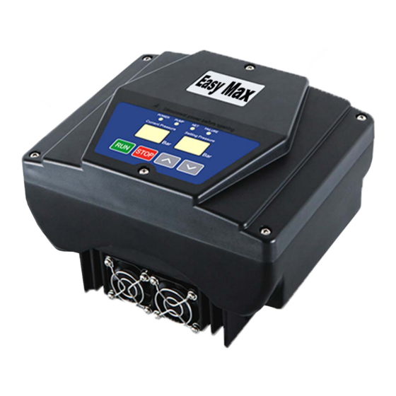
- Page 1 Manuale d’istruzioni Instructions manual Inverter per elettropompe Easy Max...
- Page 2 Inverter Easy Prima di installare e utilizzare questo prodotto, leggere attentamente le istruzioni riportate nel seguente libretto. Questo prodotto non può essere utilizzato nel campo del trattamento medico o in altri settori lavorativi che potrebbero portare ad un infortunio. - 2 -...
-
Page 3: Table Of Contents
CONTENUTI 1. Sommario 1.1 introduzione..............................3 1.2 ambito d’utilizzo..............................3 1.3 vantaggi d’utilizzo.............................3 2. sicurezza e informazioni 2.1 informazioni sull’utilizzo............................4 2.2 controllo prodotto..............................5 2.3 informazioni a riguardo delle condizioni ambientali..................5 3. aspetto, dimensioni e dati tecnici del prodotto 3.1 Aspetto e dimensioni............................6 3.1.1 Disegno dimensionale............................6 3.1.2 dati tecnici..............................7 4. -
Page 4: Introduzione
1. Sommario 1.1 introduzione Gli inverter della serie EASY garantiscono una pressione costante al sistema di approvvigionamento idrico grazie all’utilizzo della tecnologia di modulazione PWM e al processore digitale DSP. Utilizzando un inverter di frequenza combinato con una tecnologia di rilevamento della pressione, gli inverter EASY può regolare la velocità del motore in tempo reale attraverso il monitoraggio delle modifiche nella rete di tubature e regolare di conseguenza la pressione di uscita, in modo da garantire un risparmio di acqua ed elettricità. -
Page 5: Sicurezza E Informazioni
2. sicurezza e informazioni 2.1 informazioni sull’utilizzo 1. Leggere attentamente il presente libretto prima dell’installazione e utilizzo. 2. Prima di avviare il prodotto, assicurarsi che sia stata fatta la messa a terra. 3. Prestate particolare attenzione ai simboli utilizzati in questo libretto. Rischio generale di pericolo elettrico. -
Page 6: Controllo Prodotto
2. sicurezza e informazioni 1. L’installazione e l’utilizzo del prodotto deve essere in linea con le normative vigenti 2. L’installazione e la manutenzione vanno eseguiti da personale qualificato che abbia letto il presente libretto. 3. Se il motore si surriscalda in modo anormale, chiudete immediatamente la valvola di approvvigiona- mento dell’acqua e togliete l’alimentazione elettrica e contattate il centro servizi oppure il rivenditore. -
Page 7: Aspetto, Dimensioni E Dati Tecnici Del Prodotto
3. aspetto, dimensioni e dati tecnici del prodotto 3.1 Aspetto e dimensioni 3.1.1 Disegno dimensionale 1.1Kw e inferiori - 7 -... -
Page 8: Dati Tecnici
3. aspetto, dimensioni e dati tecnici del prodotto 3.1.2 dati tecnici Specifica 2.2 KW 4.0 KW 5.5 KW 7.5 KW elemento Alimentazione Monofase o trifase corrente AC (alternata) Trifase corrente AC (alternata) Voltaggio 230 V AC oppure 400V AC 400 V AC d’ingresso Frequenza 50Hz o 60 Hz... -
Page 9: Istruzioni Per L'installazione E L'utilizzo
4. Istruzioni per l’installazione e l’utilizzo 4.1. installazione e risoluzione degli errori 4.1.1 cablaggio e istruzioni per l’installazione per inverter monofase Installazione di un sistema Installazione con una pompa Installazione per autoclave autoadescante sommersa Inverter Inverter Idrosfera Idrosfera Idrosfera Inverter EASY EASY EASY... -
Page 10: Cablaggio
4. Istruzioni per l’installazione e l’utilizzo 4.2 cablaggio 4.2.1 schema di cablaggio e relative istruzioni Monofase in ingresso e monofase in uscita Monofase in ingresso e trifase uscita Schema cablaggio Schema cablaggio Al sensore alla pompa all’alimentazione Al sensore alla pompa all’alimentazione 1~230V AC 1~230V AC... -
Page 11: Utilizzo
4. Istruzioni per l’installazione e l’utilizzo 4.3 utilizzo 4.3.1 prima dell’utilizzo 1. verificare che la corrente in entrata e che l’ambiente in cui è installato l’inverter siano compatibili con le condizioni d’utilizzo. 2.verificare che il sensore di pressione sia collegato al sistema. 3. -
Page 12: Guida Ai Tasti E Alle Funzioni
4. Istruzioni per l’installazione e l’utilizzo 4.3.3 Guida ai tasti e alle funzioni Nome o Disegno Cosa serve funzione Display Indica la pressione attuale in Bar pressione attuale Alimentazione Si illumina quando l’inverter è acceso Quando la velocità del motore è regolato dall’inverter, l’indicatore lampeggia velocemente. -
Page 13: Codici E Istruzioni
4. Istruzioni per l’installazione e l’utilizzo 4.3.4 codici e istruzioni Nome Disegno Istruzioni completo codice Pressione Corrente Pressione Impostata Quando il voltaggio super i 270V appare questo codice. Se scende sotto i 260V, si ripristina il normale Protezione sovra-voltaggio stato di funzionamento. Pressione Corrente Pressione Impostata Quando il voltaggio scende sotto i 100V appare questo codice. -
Page 14: Manutenzione
5. manutenzione 5.1 informazioni a riguardo della manutenzione 1. La manutenzione va eseguita da personale qualificato. 2. Gli utenti non possono modificare senza permesso la struttura delle pompe, l’impostazione delle prestazioni ecc.… altrimenti la nostra ditta non sarà responsabile delle conseguenze. 3. - Page 15 Codici e dati tecnici 6.1 Impostazione dati tecnici e descrizione Possiamo tarare l’inverter quando è in modalità Stop. Premete i pulsanti Su e giù simultaneamente e teneteli premuti per 3 secondi. A questo punto si possono inserire i parametri desiderati. Premete il tasto “RUN” per confermare e salvare quanto impostato. Se non si fa nulla, dopo 3 secondi il sistema si resetterà...
- Page 16 Codici e dati tecnici 1.per sistemi Con un valore più alto, AC220V l’interferenza sarà minore 2.per poten- impostazione e l’onda avrà un andamento armonico. ze maggiori F004 frequenza Allo stesso tempo, più alta è 8KHz or 16KHz 8KHz di 2.2KW la la frequenza dell’inverter, portante frequenza è...
- Page 17 Codici e dati tecnici Con questo parametro si può risolvere il problema del mancato arresto in Impostare la caso di perdita dalle tubature. Prestate F008 frequenza degli particoalre attenzione a regolare tale 20Hz ~ 45Hz 25Hz arresti parametro perchè può causare riavvi frequenti della pompa.
- Page 18 Codici e dati tecnici si può impostare il numero massimo Numero massimo di pompe in funzione contemporanea- di pompe in F013 mente. Il numero masimo è 6. Il numero funzione contem- impostato lavora con la massima porta- poraneamente ta dell’acqua. questa impostazione deve essere in accordo con il voltaggio in uscita .
- Page 19 Funzioni di protezione e descrizione ripristino condizioni codice nome funzione e descrizione note automatico di ripristino ripristino Questo codice è attivato quando si automatico portezione raggiunge la temperatura limite quando la sì surriscaldamento e scatta la protezione temperatura e la potenza in uscita è bloccata. scende sotto i 20°C ripristino...
- Page 20 Funzioni di protezione e descrizione Questo codice si attiva quando il mo- Riavviate il sistema Protezione corto tore è in corto circuito. Il valore rilevato e attendete 5 minuti circuito deve raggiungere il valore limite per 5 prima di riattivare la microsecondi corrente elettrica.
- Page 21 Collegamenti (per 2 o più Inverter fino ad un massimo di 6) 7.1 Le possibilità di connessione dell’inverter: 1.Controllo connessione: Per usufruire delle funzionalità dell’inverter 485, si possono utilizzare i due cavi principali per controllare in modo indipendente il funzionamento delle pompe in parallele (massimo 6 pompe). Il circuito di massa GND non serve se la distanza è inferiore ai 100 metri.
- Page 22 Collegamenti (per 2 o più Inverter fino ad un massimo di 6) Funzioni inverter: 1. Prevenzione contro i danni da gelo: Questo programma permette l’utilizzo continuo della pompa, così da impedire all’acqua di gelarsi. 2. Riavvio automatico dopo l’arresto: quando manca la corrente elettrica, o in qualunque caso in cui la pompa smetta di funzionare, l’inverter registra le ultime impostazioni utilizzate mentre era in funzione e le utilizza al riavvio.
- Page 23 Collegamenti (per 2 o più Inverter fino ad un massimo di 6) Istruzioni per funzionamento con più pompe in linea Metodo di lavoro di default : modalità a host fisso Collegamento : i due cavi principali (0.5 mm2) possono essere usati per controllare indipendentemente il controllo parallelo delle pompe (massimo 6). 1.
- Page 24 Dati relativi a corrente in ingresso monofase, corrente in uscita trifase ingresso ingresso ingresso AC220V ingresso AC220V ritardo impostazione di AC220V AC220V valore ritardo Valore sovraccarico AC220V Codice AC220V codice sottotensione fabbrica Codice surri- codice cort Potenza valore valore sovracorrente sovracorrente corrente (A) Valore recupero...
- Page 25 Valore sovrac- Codice mancata Ingresso ingresso ingresso C110V codice codice Valore so- ingresso AC110V carico corrente codice resistenza comunicazione fra AC110V codice sotto- AC110V valore recupero codice Overload delay time(S) mancanza di sovrapres- vrapressione recupero da (A)15secondi sovraccarico campione (Ω) display e pannello sottotensione tensione...
- Page 26 Easy Max Inverter Before installing and using this product, carefully read the instructions provided in this booklet. This product cannot be used in the field of medical treatment or in other work sectors which may lead to injury. - 26 -...
- Page 27 CONTENTS 1. Table of contents 1.1introduction ................................ 3 1.2 sector of use ..............................3 1.3 use advantages ..............................3 2. safety and information 2.1 information on use ............................4 2.2 product inspection ............................. 5 2.3 information regarding environmental conditions ....................5 3.
-
Page 28: Table Of Contents
1. Table of contents 1.1 introduction The EASY series inverters ensure constant pressure to the water supply system thanks to the use of PWM modula- tion technology and the DSP digital processor. By using a frequency inverter combined with pressure detecting technology, the EASY inverter can adjust the motor speed in real time by monitoring the changes in the piping network and adjusting the output pressure accordingly, in order to assure water and electricity savings. -
Page 29: Safety And Information
2. safety and information 2.1 information on use 1. Carefully read this booklet before installation and use. 2. Before starting the product, make sure earthing has been performed. 3. Pay particular attention to the symbols used in this booklet. General electrical hazard risk. If ignored, it may cause damage to the electrical pump and to persons. Hazard caused by electrical equipment. -
Page 30: Product Inspection
2. safety and information 1. Product installation and use must comply with the standards in force. 2. Installation and maintenance must be performed by qualified personnel who have read this booklet. 3. If the motor overheats in an abnormal manner, immediately close the water supply valve and discon- nect the electrical power supply and contact the service centre or the dealer. -
Page 31: Product Appearance, Dimensions And Technical Data
3. product appearance, dimensions and technical data 3.1 Appearance and dimensions 3.1.1 Dimensional drawing 1.1Kw and lower - 31 -... -
Page 32: Technical Data
3. product appearance, dimensions and technical data 3.1.2 technical data Element 2.2 KW 4.0 KW 5.5 KW 7.5 KW specification Power supply Single-phase or three-phase AC current (alternated) Three-phase AC current (alternated) Input voltage 230 V AC oppure 400V AC 400 V AC Frequency 50Hz o 60 Hz... -
Page 33: Instructions For Installation And Use
4. Instructions for installation and use 4.1. installation and troubleshooting 4.1.1 wiring and instructions to install single-phase inverter Installation for autoclave Installing a self-priming system Installation with submerged pump Easy Easy Hydrosphere Hydrosphere Hydrosphere Easy Inverter Inverter Inverter Pressure Pressure Pressure transducer transducer... -
Page 34: Wiring
4. Instructions for installation and use 4.2 wiring 4.2.1 wiring diagram and relative instructions Single-phase input and single-phase output Single-phase input and three-phase output Wiring diagram Wiring diagram To the to the power To the to the power to the pump sensor to the pump supply... -
Page 35: Use
4. Instructions for installation and use 4.3 use 4.3.1 before use 1. Check that the input current and that the environment in which the inverter is installed are compatible with the use conditions. 2. check that the pressure sensor is connected to the system. 3. -
Page 36: Keys And Functions Guide
4. Instructions for installation and use 4.3.3 Keys and functions guide Name or Drawing What it is for function Current pressure Indicates the current pressure in Bar display Power supply It lights up when the inverter is on When the motor speed is adjusted by the inverter, the indicator flashes quickly. -
Page 37: Codes And Instructions
4. Instructions for installation and use 4.3.4 codes and instructions Full code name Drawing Instructions Pressione Corrente Pressione Impostata This code appears when voltage exceeds 270V. If it drops below 260V, Overvoltage protection normal operating status is restored. Pressione Corrente Pressione Impostata This code appears when voltage drops below 100V. -
Page 38: Information On Maintenance
5. maintenance 5.1 information on maintenance 1. Maintenance must be performed by qualified personnel. 2. users cannot change the pumps structure, performance settings etc... without permission, otherwise our company shall not be responsible for the consequences. 3. During summer, make sure the premises where the pump is installed are well ventilated, but that it is not exposed to direct sunlight or rain. - Page 39 Codes and technical data 6.1 Technical data setting and description The inverter can be calibrated when it is in Stop mode. Press the Up and Down buttons simultaneously and hold them down for 3 seconds. Now the desired parameters can be entered. Press the “RUN” key to confirm and save the settings. If nothing is done, the system will reset to the previous parameters after 3 seconds.
- Page 40 Codes and technical data With a higher value, 1.for AC220V the interference will be lower systems and the wave will have 2.for powers carrier frequency a harmonic pattern. greater than F004 8KHz or 16KHz 8KHz setting At the same time, 2.2KW the the higher the inverter frequency, frequency...
- Page 41 Codes and technical data With this parameter you may solve the problem of no stop due to pipes leaks. Pay particular attention when Set the stops F008 adjusting this parameter since it 20Hz ~ 45Hz 25Hz frequency may cause frequent pump restarts. The parameter always goes at more than 30 Hz.
- Page 42 Codes and technical data The maximum number of pumps Maximum number operating simultaneously can be set. F013 of pumps operating The maximum number is 6. simultaneously The number set operates with maximum water flow rate. this setting must match the output voltage.
- Page 43 Protection functions and description automatic restoring code name function and description notes restore conditions This code is activated when the limit automatic restore overheating temperature is reached and the when the protection protection is triggered and the temperature output power is blocked. drops below 20°C automatic restore when the input voltage...
- Page 44 Protection functions and description This code activates when the motor Restart the system Short circuit suffers a short circuit. The value and wait 5 minutes protection detected must reach the limit before restoring value for 5 microseconds electrical power. automatic restore Water over This code activates when when the pressure...
- Page 45 Connections (for 2 or more Inverters up to 6) 7.1 Inverter connection options: 1.Check connection: In order to use the functionalities of the 485 inverter, you may use the two main cables to independently control the operation of the parallel pumps (6 pumps maximum). The GND earth circuit is not required if the distance is less than 100 metres. Above 100 metres, connect the GND geodesic earth circuit with copper wire.
- Page 46 Connections (for 2 or more Inverters up to 6) Inverter functions: 1. Freezing damage prevention: This program enables continuous pump use, so as to prevent the water from freezing. 2. Automatic restart after stop: when there is no electrical power, or in any case where the pump stops functioning, the inverter stores the last settings used while it was running and uses them again on restart.
- Page 47 Connections (for 2 or more Inverters up to 6) Instructions for operation with multiple pumps in line Default working method: fixed hose mode Connection: the two main cables (0.5 mm2) can be used to independently check the pumps parallel control (6 maximum). 1.
- Page 48 Data relative to single-phase input current, three-phase output current input AC220V input AC220V input AC220V AC220V input AC220V overvoltage overcurrent Current overload Undervoltage AC220V code overheating factory Ooverheating short circuit overcurrent Power undervoltage Undervoltage recovery overvoltage undervoltage value value (A) 5 seconds code Overvoltage overvoltage...
- Page 49 Current overload No communica- input C110V sample Overpressure Input AC110V input AC110V input AC110V value (A) no pressure overpressure tion between di- undervoltage overvoltage overvoltage overload code Overload delay time(S) resistance value undervoltage recovery from overvoltage 15 seconds code code splay and control code recovery value...
- Page 50 NOTES - 50 -...
- Page 51 NOTES - 51 -...
- Page 52 Déclaration CE de Conformité (P2 2,2 kW - V/arvutatud Hz, kõverpunkt max. tootlikusel LpA mõõdetud 1,6m) ● 2000/14/CE Nous declarons que les articles de ce livret sont déclarés conformes aux Directives suivantes: (P2<2,2 kW - V/Hz d’après plaque, point en courbe au Qmax)→ LWA mesuré 84 dBA/LWA garanti 85 dBA/Procédure suivie: Annexe V ●...
Need help?
Do you have a question about the Easy Max and is the answer not in the manual?
Questions and answers