
Summary of Contents for CAGSAN MERDIVEN ProTUBE L
- Page 1 Assembly and use guide PROFESSIONAL SCAFFOLDING SYSTEMS ( ProTUBE L - S - F ) The instructions for the assembly and use shall be followed carefully EN1004 201612-IE-1210...
-
Page 2: Table Of Contents
3. ProTUBE L (Wide) Aluminum Scaffold System ..........8 3.1 ProTUBE L Configuration Table ...............9 3.2 ProTUBE L6 Scaffold Assembly Method ............10 3.3 ProTUBE L (Wide) Aluminum Scaffold System 3D Pictures ....16-17 3.4 ProTUBE L Scaffold System Compounds ............18 4. ProTUBE S (Narrow) Aluminum Scaffold System ..........19 .1 ProTUBE S Configuration Table ................19... -
Page 3: Introduction
ProTUBE Scaffold is used. Max Platform Height 2. General Product Indoor Outdoor ProTUBE L 12,20 m. 4,63 m. For Standard ProTUBE Scaffold configu- ProTUBE L 12,20 m. 8,00 m. rations see the configurations table in this ProTUBE S 6,50 m. -
Page 4: Necessary Additional Instructions For Usage Of Protube Scaffolds
• ProTUBE Scaffolds should not be used for storm, snow, ice, excessive rain or lightning • Do not lift or held with a crane Pro- TUBE Scaffolds. • ProTUBE Scaffolds should not be used for access to other structures. • Standard configuration calculations cannot include canvas and/or adverti- sing display usage calculations. -
Page 5: Check List For Usage Of Protube Scaffold
2.3 Check List for Usage of Pro- on ProTUBE Scaffolds. • Take necessary precautions towards TUBE Scaffold the environmental factors to work sa- fely on ProTUBE Scaffolds. In the first usage or reusage of a ProTU- • Use extra safety guardrails when nee- BE Scaffold whose installation is comp- ded for safety and legislation. -
Page 6: Examination, Storage And Maintenance
tallation. • All locking pins are on their actual lo- cation on the scaffold and are locked. 2.4 Examination, Storage and Maintenance • ProTUBE Scaffolds parts should be carried and transported carefully in order to avoid damages. • Storage should be organized in a way •... -
Page 7: Assembly And/Or Repair Of Spare Parts
they will all contact with the surface faults are not immediately informed the guarantee shall be void. In order 2.7 Assembly and/or Repair of to make a request under the guarantee scope, Çağsan Merdiven or Çağsan Spare Parts Merdiven dealer should be informed about the product delivery and an in- Take in to account the national regulations voice should be submitted. - Page 8 • Check the condition of the wood. • Check the trapdoors for correct functi- 2.10 Locking the Wheels oning. Toeboards You need to push the brake pedal in or- • Check the condition of the wood. der to lock the wheels. You need to lift the •...
-
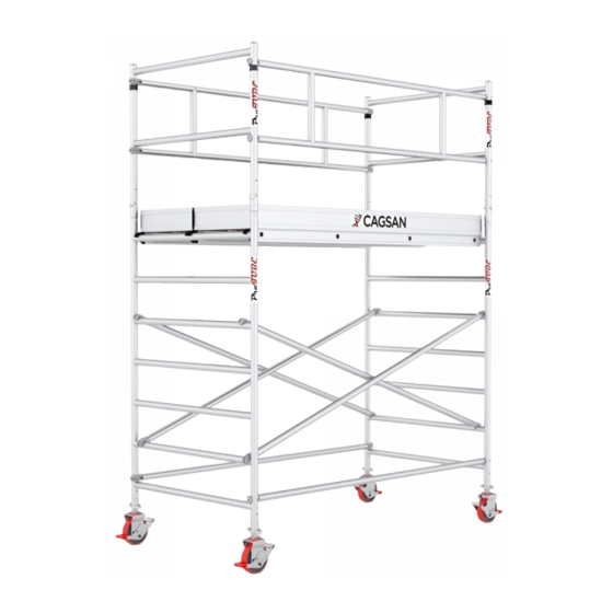
Page 9: Protube L (Wide) Aluminum Scaffold System
3. ProTUBE L (Wide) Aluminum Scaffold System 3.1 ProTUBE L Configuration Table 2,30 4,40 6,50 8,00 10,70 12,20 Platform Height (m.) 4,10 6,20 8,30 9,80 12,50 14,00 Working Height (m.) Explanations Item Code Weight Piece (kg.) Modular Frame 7 Steps... -
Page 10: Protube L6 Scaffold Assembly Method
3.2 ProTUBE L6 Scaffold As- sembly Method 1. Place the castors to the seats in the modular frames. (Diagram 1) 3. Place 2 diagonal braces reciprocally between the 2nd steps and 5th steps of the modular frame. Make sure the aluminum cast clamps on the corners of the connections are safely seated and locked.(Diagram 4) - Page 11 4. Then place the 1 covered platform to the 3rd step. Balance the scaf- fold according to the long sides and short sides by using a water scale. (Diagram 5) You need to turn the sc- rewed tool on the wheels right and left in order to balance your scaffold.
- Page 12 8. Then place the platform without trap- door in line with the 3rd step of the 2nd floor while you are on the 1st floor. After this process your scaffold will rise for another floor. (Diagram 10) 7. Place the 4 cross connection parts to the modular frames you just placed.
- Page 13 9. Get on top of the platform you placed on the 2nd floor and put the guardrail frames into the fitting tool of the mo- dular frames of the 2nd floor. Pass the security pint of the guardrail frames from the holes of the modular frames and lock them.
- Page 14 11. Pass through the platform by lifting the trapdoor of the platform with the trapdoor you placed on top and sit at the corner. Fix the horizontal security connections of the guardrail. Make sure the aluminum cast clamps are sa- fely seated and locked.
- Page 15 13. Place the wooden pad in a way that it will surround the 2 platforms at the top. (Diagram 15) You need to repeat the steps 6-7-8 in order 14. Your ProTUBE L6 coded product to increase the height of your scaffold. with 4.40 m.
-
Page 18: Protube L Scaffold System Compounds
3.4 ProTUBE L Scaffold System Compounds PT223M Modular Frame 7 Steps PT263M Modular Frame 5 Steps PT110K Guardrail Frame PT259H PT259Y Guardrail Braces (H) Horizontal Braces PT275C Diagonal Braces PT258KP Platform (With Trapdoor) PT258K Platform (Without Trapdoor) PT200TE Castor PT276PA... -
Page 19: Protube S (Narrow) Aluminum Scaffold System
4. ProTUBE S (Narrow) Aluminum Scaffold System 4.1 ProTUBE S Configuration Table 2,30 4,40 6,50 Platform Height (m.) 4,10 6,20 8,30 Working Height (m.) Explanation Item Code Weight (kg.) Modular Frame 7 Steps PTS223M Guardrail Frame PTS110K Platform (With Trapdoor) PT258KP 23,5 Diagonal Braces... -
Page 20: Protube S6 Scaffold Assembly Method
4.2 ProTUBE S6 Scaffold Assembly Method 1. Place the wheeled legs to the seats in the modular frames. (Drawing 1) 3. Place 2 diagonal braces reciprocally between the 2nd steps and 5th steps of the modular frame. Make sure the aluminum cast clamps on the corners of the connections are safely seated and locked (Drawing 4). - Page 21 4. 4Fix 4 balance legs (support) to the scaffold. Connect the connection tool between the short part of the balance legs to the gap between 2nd step and 3rd step and its long part to the gap between 6th step and 7th step. Af- ter making sure the tools completely grasp the carrier profile, tighten the bakalite heads by turning.
- Page 22 6. Place the 4 cross connection parts to the modular frames you just pla- ced. Make sure the aluminum cast clamps are safely seated and locked. (Drawing 9) 7. Then carry it upwards onto the 7th step of the 2nd floor and fix it. Don’t forget to open the wind lock while di- sassembling the platforms.
- Page 23 8. Get on top of the platform you placed on the 2nd floor and put the guardrail frames into the fitting tool of the mo- dular frames of the 2nd floor. Pass the security pint of the guardrail frames from the holes of the modular frames and lock them (Drawing 11).
- Page 24 10. Place the wooden pad in a way that it will surround the platform at the top (Drawing 13). You need to repeat the steps 5-6-7 in order to increase the height of your scaffold. 11. Your ProTUBE F6 coded product with 4.40 m.
-
Page 26: Protube S Scaffold Systems Compounds
4.4 ProTUBE S Scaffold Systems Compounds PTS223M Modular Frame 7 Steps PTS110K Guardrail Frame PT259H PT259Y Guardrail Braces (H) Horizontal Braces PT275C Diagonal Braces PT258KP Platform (With Trapdoor) PT200TE Castor PT276PA Stabilizer PTS302TM Toeboard... -
Page 27: Protube F (Foldable) Aluminum Scaffold System
5. ProTUBE F Karelia Aluminum Scaffold System 5.1 ProTUBE F Configuration Table F180 F360 Platform Height (m.) 0,90 1,80 3,60 Working Height (m.) 2,70 3,60 5,40 Explanation Item Code Weight Foldable Modular Frame PTF223M 23,0 Modular Frame 6 Steps PTF223ME Guardrail Frame PTS110K Platform (With Trapdoor) -
Page 28: Protube F6 Scaffold Assembly Method
5.2 ProTUBE F Scaffold Assembly Method 1. Place the wheeled legs to the seats in the modular frames (Drawing 1) 3. Place the 1 horizontal connection onto the 1st step and fasten it to the modu- lar frame from the interior part. Fix 2 diagonal braces between the 2nd step to 5th step. - Page 29 4. Then place the 1 covered platform to 6. Fix 4 balance legs (support) to the the 7th step. Balance the scaffold ac- scaffold. Connect the connection tool cording to the long sides and short si- between the short part of the balance des by using water scale (Drawing 5) legs to the gap between 1nd step and 2rd step and its long part to the gap...
- Page 30 8. Then carry it upwards onto the 7th 9. Get on top of the platform you placed step of the 2nd floor and fix it. Don’t on the 2nd floor and put the guardrail forget to open the wind lock while di- frames into the fitting tool of the mo- sassembling the platforms.
- Page 31 10. Fix the horizontal security connecti- ons of the guardrail. Make sure the aluminum cast clamps are safely sea- ted and locked (Drawing 11)
- Page 32 11. Place the wooden pad in a way that it will surround the platform at the top (Drawing 12) Thank you for choosing Çağsan Merdiven products. 12. Your ProTUBE F360 coded product with 4.40 m. stepping height is ready for usage (Drawing 13)
-
Page 34: Protube F Scaffold Systems Compounds
5.4 ProTUBE F Karelia Scaffold Systems Compounds PTS223M PTS223ME Modular Frame 6 Steps Modular Frame 6 Steps PTS110K Guardrail Frame PTF182H PTF182Y Guardrail Braces (H) Horizontal Braces PTF202C Diagonal Braces PTF183KP Platform (With Trapdoor) PT125TE Castor PT276PA Stabilizer PTF180TM Toeboard... - Page 35 ........................... .
- Page 36 Cagsan Merdiven Erisim Ekipmanları San. Tic. Ltd. Sti. Dilovası Organize Sanayi Bolgesi 3. kisim , Meric Cad. No: 1 Muallim Koyu, Gebze - Kocaeli / TURKEY...
Need help?
Do you have a question about the ProTUBE L and is the answer not in the manual?
Questions and answers