
Related Manuals for Swagelok 20 Series


Summary of Contents for Swagelok 20 Series
- Page 1 Series 20 Weld Head User’s Manual English....... . . 1...
- Page 2 Series 20 Weld Head User’s Manual...
- Page 3 Weld Head User’s Manual 13-205R4.indb 1 2/1/13 2:43 PM...
-
Page 4: Table Of Contents
Series 20 Weld Head User’s Manual Contents Weld Head . . . . . . . . . . . . . . . . . . . . . . . . . . . . . . . 3 Fixture Block . -
Page 5: Weld Head
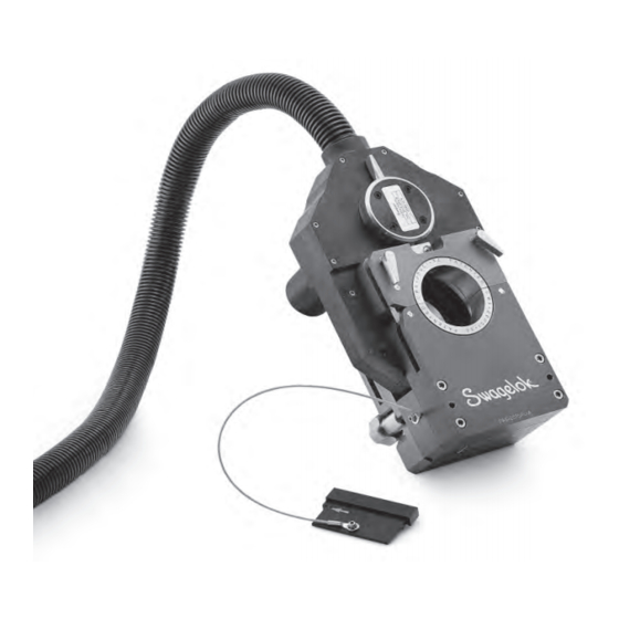
Series 20 Weld Head User’s Manual Weld Head The Series 20 SWS weld head delivers consistent, precise welds for outside tubing diameters from 1/2 to 2 in. and 12 to 52 mm and pipe diameters ranging from 1/4 to 1 1/4 in. and 10.2 to 48.3 mm. A DC motor in the weld head drives a rotor, which carries the tungsten electrode around the weld joint. -
Page 6: Unpacking The Weld Head Components
• weld head • arc gap gage • electrode package • tool package Perform the following steps when your Swagelok Series 20 Weld Head arrives: 1. Inspect the container for damage. 2. Remove the components from the container. 3. Check the items for any damage. -
Page 7: Installing The Weld Head
This connection is the positive (+) terminal of the weld head. 5. Insert the weld head shielding gas connector into the Swagelok Quick-Connect stem labeled TO WELD HEAD. Ensure that the connector is firmly attached. This connection provides shielding gas to the weld head through a mass flow controller (MFC) in the power supply. -
Page 8: Installing The Electrode In The Weld Head
Series 20 Weld Head User’s Manual Installing the Electrode in the Weld Head This Swagelok weld head comes with a selection of electrodes. The following instructions show how to properly install an electrode in the weld head. Selecting the Proper Electrode Electrode length and diameter depend on your weld head model and the outside diameter of the work piece being welded. -
Page 9: Electrode Geometry
Series 20 Weld Head User’s Manual Electrode Geometry This illustration shows the electrode shape Swagelok suggests. Properly ground electrodes provide consistent, repeatable welds. Pre-ground electrodes are available from your Swagelok representative. See your parts list for ordering information. The electrode part numbers are assigned as follows: CWS –... -
Page 10: Calculating Arc Gap Gage Settings
Series 20 Weld Head User’s Manual Calculating Arc Gap Gage Settings To determine the arc gap gage setting for a specific arc gap, use the formula below. Arc Gap Gauge Setting Where A = largest OD on the weld end of the tubing or fitting (welding diameter). B = Arc gap gage diameter C = desired arc gap Figure 7... -
Page 11: Setting The Arc Gap
Series 20 Weld Head User’s Manual Setting the Arc Gap The proper arc gap setting facilitates control of the weld and improves consistency. The following steps cover how to set the arc gap. The arc gap is set by using the arc gap gage provided with the weld head. - Page 12 Series 20 Weld Head User’s Manual Table 2 SWS-20H Arc Gap Gage Dia. 3.118 in. Setting Setting Setting Setting Setting Setting Setting Setting Setting Setting Nominal Actual 0 .030 in . 0 .040 in . 0 .050 in . 0 .060 in . 0 .070 in . 0,5 mm 0,64 mm 0,76 mm...
-
Page 13: Inserting The Electrode Into A Rotor
Series 20 Weld Head User’s Manual Inserting the Electrode into a Rotor 1. Without the fixture block attached, press ELECTRODE CHANGE on the operator panel. The electrode will move to the position shown in Figure 9. 2. Loosen the two electrode clamping screws. If you are replacing the electrode, remove the electrode. -
Page 14: Setting The Arc Gap
Series 20 Weld Head User’s Manual Setting the Arc Gap 1. Use JOG or ELECTRODE CHANGE to position the rotor as shown. This allows access to the electrode clamping screws. 2. Insert the arc gap gage into the rotor. See Figure 10(A). 3. -
Page 15: Preparing The Work
Series 20 Weld Head User’s Manual Preparing the Work It is important to prepare the tube pieces properly before welding. Refer to Figure 11. Tubing must be square and burr-free to ensure repeatable, high- quality autogenous fusion welds. Cut the tubing to length with a hacksaw or tube cutter. -
Page 16: Fixturing The Work
Series 20 Weld Head User’s Manual Fixturing the Work Select or configure the appropriate fixture block. Select the collets to match the work outside diameter. Selecting the Fixture Block and Collets 1. Select the fixture block that accepts the outside diameter of the tube to be welded. - Page 17 Series 20 Weld Head User’s Manual Installing the Collets in a Tube Fixture Block 1. Release both levers and open the tube fixture block. See Figure Figure 12 Opening the Fixture Block 13-205R4.indb 15 2/1/13 2:43 PM...
- Page 18 Series 20 Weld Head User’s Manual 2. Install the collet halves in both the top and bottom side plates and tighten the collet screws. Make sure the collet shoulder is flush against the fixture side plate. See Figure 13. Fixture Side Plate Collet Shoulder Figure 13...
- Page 19 3. Lock down the top side plate. See Figure 15(B). 4. Remove the centering gage. Figure 14 Place the Centering Gage Note: When welding a Swagelok ATW fitting to tubing, butt the tubing against the centering gage first. Figure 15 Placing First Work Piece in the Fixture Block 13-205R4.indb 17...
- Page 20 Series 20 Weld Head User’s Manual 5. Butt the second work piece against the first work piece, and lock down the top side plate. See Figure 16. 6. Inspect 360° around the weld joint for fit and alignment. If the alignment is not correct proceed to the next section.
- Page 21 Series 20 Weld Head User’s Manual Adjusting the Fixture Block The modular design of the Series 20 Fixture Block allows you to assemble the block to meet a variety of welding requirements. To align tubing in the fixture block follow these steps: 1.
- Page 22 Series 20 Weld Head User’s Manual Mating the Weld Head to the Fixture Block 1. Rotate the locking lever on the weld head counter-clockwise until it stops. See Figure 21. 2. Insert the weld head into the fixture block. See Figure 22(A). 3.
-
Page 23: Maintenance
Series 20 Weld Head User’s Manual Maintenance To ensure your Swagelok Welding System (SWS) equipment is always Note: in proper working order, you must perform periodic maintenance on the system components. If you experience problems while performing the procedures in this section, refer to the... - Page 24 Series 20 Weld Head User’s Manual Fixture Block Daily Maintenance Non-Anodized Surfaces At the start of each work day: Under the Collets 1. Inspect the fixture block for cleanliness, wear and damage. See Figure 23. 2. Remove dirt, carbon, and vapor deposits from the fixture block with a clean, soft cloth.
- Page 25 Repeat for the other side of the fixture block. If any wear or damage is found or the fixture Contact your authorized Swagelok representative to return the fixture block is not properly securing the work piece, block for service.
- Page 26 Series 20 Weld Head User’s Manual Weld Head Daily Maintenance Perform weld head maintenance daily and every 500 to 700 welds. Depending on usage and wear, maintenance may be performed before WARNING! the 500-weld mark. Disconnect the WORK and ELECTRODE cables from the power supply before performing the adjustment or At the start of each work day:...
- Page 27 Series 20 Weld Head User’s Manual Weld Head Disassembly and Cleaning This section describes how to disassemble the weld head and rotor. Weld Head Screws Locking Ring To disassemble the weld head, follow these steps: Plate Locking Ring 1. Blow any loose material from the weld head assembly with clean, low-pressure air.
- Page 28 Series 20 Weld Head User’s Manual 5. Remove the weld head housing screws from the housing. Using a slight rocking motion, carefully separate the work side of the weld Housing head housing from the motor side. See Figure 28. Screws 6.
- Page 29 Series 20 Weld Head User’s Manual 9. Examine the brush. See Figure 31. Brush Inspect and clean the brush using the following steps: a. Check the brush for excessive wear. b. Verify that the brush has a groove. Replace the brush if the groove is not present.
- Page 30 Series 20 Weld Head User’s Manual Rotor To disassemble the rotor, follow these steps: Rotor Screw Electrode 1. Remove the rotor screws and the electrode clamping plate screws Clamping from the rotor. Remove the electrode from the ceramic insert. See Plate Screw Figure 34.
- Page 31 Series 20 Weld Head User’s Manual 7. Remove the ceramic insert. See Figure 37. Ceramic Insert 8. Inspect the ceramic insert. If it has carbon or other deposits, clean it with a fine-grit abrasive pad or soft nylon brush. 9. Remove the electrode clamping plate. Clean it with a fine-grit abrasive pad.
- Page 32 Series 20 Weld Head User’s Manual 13-205R4.indb 30 2/1/13 2:43 PM...
-
Page 33: Parts Drawings
This section includes exploded assembly drawings and associated parts lists. These drawings are provided as a guide to identifying part names. For specific part ordering information, contact your authorized Swagelok representative. The parts identified in this section include: • SWS-20H Weld Head • SWS-20H Motor and Power Block Assembly... - Page 34 Series 20 Weld Head User’s Manual Figure 40 SWS-20H Weld Head 13-205R4.indb 32 2/1/13 2:43 PM...
- Page 35 Plastic Socket Head Cap Screw, 13105 6-32 x 0.437 in. SS Dowel Pin Split Lock Washer 13208 For part ordering information, contact your authorized Swagelok representative. * Not available as a field replacement spare part. 13-205R4.indb 33 2/1/13 2:43 PM...
- Page 36 Series 20 Weld Head User’s Manual Figure 41 SWS-20H Motor and Power Block Assembly 13-205R4.indb 34 2/1/13 2:43 PM...
- Page 37 SS Socket Head Cap Screw, 2-56 x 0.187 in. 13111 Wire Ring Terminal SS Slotted Head Screw, 4-40 x 0.250 in. 188-21066-RCEU For part ordering information, contact your authorized Swagelok representative. * Not available as a field replacement spare part. 13-205R4.indb 35 2/1/13 2:43 PM...
- Page 38 Series 20 Weld Head User’s Manual Figure 42 SWS-20H Rotor Assembly 13-205R4.indb 36 2/1/13 2:43 PM...
- Page 39 SS Socket Head Cap Screw, 2-56 x 0.250 in. 13176 Electrode Clamping Plate 11306 Ceramic Insert 11210 See Electrode Chart (page 4) For part ordering information, contact your authorized Swagelok representative. * Not available as a field replacement spare part. 13-205R4.indb 37 2/1/13 2:43 PM...
- Page 40 Series 20 Weld Head User’s Manual 18 14 Figure 43 SWS-20TFB-A Tube Fixture Block 13-205R4.indb 38 2/1/13 2:43 PM...
- Page 41 SS #4 External Star Washer 13171 Centering Gage SWS-20CG-A 12 in. Lanyard 13231 SS #10 External Star Washer 13131 For part ordering information, contact your authorized Swagelok representative. * Not available as a field replacement spare part. 13-205R4.indb 39 2/1/13 2:43 PM...
- Page 42 Series 20 Weld Head User’s Manual Figure 44 SWS-20FSP1R Special Purpose Side Plate 13-205R4.indb 40 2/1/13 2:43 PM...
- Page 43 SS Set Screw, 4-40 x 0.125 in. 12132 Latch Holder (right bottom) 12314 Threaded Insert Dowel Pin For part ordering information, contact your authorized Swagelok representative. * Not available as a field replacement spare part. 13-205R4.indb 41 2/1/13 2:43 PM...
- Page 44 Series 20 Weld Head User’s Manual Figure 45 SWS-20FSP1L Special Purpose Side Plate 13-205R4.indb 42 2/1/13 2:43 PM...
- Page 45 SS Flat Head Screw, 6-32 x 0.313 in. 13318 Dowel Pin Locking Tab 12360 Lever Cam Assembly 12130-2 Threaded Insert For part ordering information, contact your authorized Swagelok representative. * Not available as a field replacement spare part. 13-205R4.indb 43 2/1/13 2:43 PM...
- Page 46 Series 20 Weld Head User’s Manual Warranty Information Swagelok products are backed by The Swagelok Limited Lifetime Warranty. For a copy, visit swagelok.com or contact your authorized Swagelok representative. 13-205R4.indb 44 2/1/13 2:43 PM...
- Page 47 シリーズ20 シリーズ20 ウェルド・ヘッド ユーザー ・ マニュアル...
- Page 48 46 シリーズ 20 ウェルド ・ ヘッド ユーザー ・ マニュアル 目次 ウェルド・ヘッド ......47 フィクスチャー・ブロック...
-
Page 49: ウェルド・ヘッド
シリーズ 20 ウェルド ・ ヘッド ユーザー ・ マニュアル 47 ウェルド・ヘッド Swagelok ウェルディング ・ システム ( SWS ) シリーズ 20 ウェルド ・ ヘッドは 、 チューブ 外径 サイズ 1/2 インチから 2 インチまで 、 12 mm から 52 mm まで 、 パイプ ・ サイズ... -
Page 50: ウェルド・ヘッド運送用ケースの開梱
• アーク ・ ギャップ ・ ゲージ • 電極 パック • 工具 セット Swagelok シリーズ 20 ウェルド ・ ヘッド 入荷 の 際 は 、以下 の 点 についてご 確認 ください 。 1. 運送用 ケースに 損傷 がないか 検査 します 。 2. 運送用 ケースから 部品 を 取 り 出 します 。... -
Page 51: ウェルド・ヘッドの取り付け
定 します 。 この 接続 が 、 ウェルド ・ ヘッドの 正(+) のターミナルです 。 5. ウェルド ・ ヘッド ・ シールド ・ ガス 用 コネクターを 、 「 TO WELDHEAD ( ウェルド ・ ヘッドへ ) 」 と 表示 された Swagelok クイック ・ コネクツ ・ ステムに 差 し 込 みます 。 コネクターがしっかりと 装着 されていることを... -
Page 52: ウェルド・ヘッドへの電極の取り付け
50 シリーズ 20 ウェルド ・ ヘッド ユーザー ・ マニュアル ウェルド・ヘッドへの電極の取り付け Swagelok ウェルド ・ ヘッドには 電極 パックが 付属 しています 。以下 の 手 順 に 従 って 、電極 をウェルド ・ ヘッドに 正 しく 取 り 付 けてください 。 適切な電極の選択 電極 の 長 さおよび 直径 は 、使用 するウェルド ・ ヘッド ・ モデルおよび 溶接... -
Page 53: 電極の形状
シリーズ 20 ウェルド ・ ヘッド ユーザー ・ マニュアル 51 電極の形状 この 図 は 、 スウェージロックが 推奨 する 電極 の 形状 を 示 しています 。適切 に 研削 された 電極 を 使用 すると 、精度 の 高 い 溶接 を 繰 り 返 し 行 うことがで きます... -
Page 54: アーク・ギャップ・ゲージ設定値の算出
52 シリーズ 20 ウェルド ・ ヘッド ユーザー ・ マニュアル アーク・ギャップ・ゲージ設定値の算出 特定 のアーク ・ ギャップ 用 のアーク ・ ギャップ ・ ゲージ 設定値 を 算出 する 際 は 、以下 の 公式 を 使用 してください 。 アーク・ギャップ・ゲージ 設定値 ここで、 チューブまたは 継手 の 溶接 エンドの 最大外径 サイズ (溶接物 の 直径) アーク... -
Page 55: アーク・ギャップの設定
シリーズ 20 ウェルド ・ ヘッド ユーザー ・ マニュアル 53 アーク・ギャップの設定 アーク ・ ギャップ 設定 を 正 しく 行 うことで 溶接 を 容易 にコントロールする ことができるため 、 一貫 した 溶接 を 行 うことができます 。以下 の 手順 に 従 っ て 、 アーク ・ ギャップの 設定 を 行 ってください 。 アーク... - Page 56 54 シリーズ 20 ウェルド ・ ヘッド ユーザー ・ マニュアル 表 2 : SWS-20H ( アーク ・ ギャップ ・ ゲージ 直径: 3.118 インチ ) 0.5 mm の 0.030 の 0.040 の 0.050 の 0.060 の 0.070 の 0.64 mm の 0.76 mm の 1.02 mm の...
-
Page 57: 電極のローターへの挿入
シリーズ 20 ウェルド ・ ヘッド ユーザー ・ マニュアル 55 電極のローターへの挿入 1. フィクスチャー ・ ブロックを 取 り 付 けていない 状態 で 、本体 スイッチ ・ パネルの 「電極交換」 を 押 します 。電極 が 図 9 の 位置 に 移動 します 。 2. 2 個 の 電極固定 ねじを 緩 めます 。電極 を 交換 する 場合 は 、電極 を 取 り 外 します... -
Page 58: アーク・ギャップの設定
56 シリーズ 20 ウェルド ・ ヘッド ユーザー ・ マニュアル アーク・ギャップの設定 1. 「ジョグ」 または 「電極交換」 を 押 してローターを 適切 な 位置(図参照) にセットします 。 これで 電極固定 ねじが 確認 できるようになります 。 2. アーク ・ ギャップ ・ ゲージをローターに 差 し 込 みます 。図 10 ( A ) をご 参照... -
Page 59: 溶接物の準備
シリーズ 20 ウェルド ・ ヘッド ユーザー ・ マニュアル 57 溶接物の準備 溶接前 に 、 適切 にチューブを 準備 することが 重要 です 。図 11 をご 参照 くだ さい 。 再現性 のある 高品質 な 自生融解溶接 を 確実 に 行 うためには 、 チューブは 厳 密 に 直角 かつバリのないものでなければなりません 。 チューブを 切断 する 場合... -
Page 60: 溶接物の固定
58 シリーズ 20 ウェルド ・ ヘッド ユーザー ・ マニュアル 溶接物の固定 適切 なフィクスチャー ・ ブロックを 選択 または 構成 します 。溶接物 の 外径 サイズに 適合 するコレットを 選択 します 。 フィクスチャー・ブロックおよびコレットの選択 1. 溶接 するチューブの 外径 サイズに 適合 するフィクスチャー ・ ブロックを 選 びます 。表 6 をご 参照 ください 。 表... - Page 61 シリーズ 20 ウェルド ・ ヘッド ユーザー ・ マニュアル 59 チューブ用フィクスチャー・ブロック内への コレットの取り付け 1. 両方 のレバーを 外 してチューブ 用 フィクスチャー ・ ブロックを 開 きま す 。図 12 をご 参照 ください 。 図 12 : フィクスチャー ・ ブロックを 開 く...
- Page 62 60 シリーズ 20 ウェルド ・ ヘッド ユーザー ・ マニュアル 2. 上部 および 下部 サイド ・ プレートの 両方 にコレットを 取 り 付 け 、 コレッ ト 止 めネジを 締 め 付 けます 。 コレットの 肩 とフィクスチャー ・ サイド ・ プレートに 段差 がないことを 確認 します 。図 13 をご...
- Page 63 4. センタリング ・ ゲージを 取 り 外 します 。 図 14 : センタリング ・ ゲージをセットする 注: Swagelok ATW 継手 をチューブに 溶接 する 際 は 、 最初 にチューブをセンタリング ・ ゲージに 突 き 合 わせてください 。 図 15 :最初 の 溶接物 をフィクスチャー ・ ブロックにセットする...
- Page 64 62 シリーズ 20 ウェルド ・ ヘッド ユーザー ・ マニュアル 5. 2 つ 目 の 溶接物 を 最初 の 溶接物 に 突 き 合 わせてから 、 上部 サイド ・ プレー トを 閉 じて 固定 します 。図 16 をご 参照 ください 。 6.
- Page 65 シリーズ 20 ウェルド ・ ヘッド ユーザー ・ マニュアル 63 フィクスチャー・ブロックの調節 シリーズ 20 フィクスチャー ・ ブロックはモジュラー ・ デザインを 採用 し ているため 、 さまざまな 溶接要件 に 合 わせてブロックを 組 み 立 てることが できます 。 以下 の 手順 に 従 って 、 フィクスチャー ・ ブロック 内 でのチューブの 位置合 わせを...
- Page 66 64 シリーズ 20 ウェルド ・ ヘッド ユーザー ・ マニュアル ウェルド・ヘッドとフィクスチャー・ブロックの取り付け 1. ウェルド ・ ヘッドのロッキング ・ レバーを 反時計回 りにまわします (止 まるところまで ) 。図 21 をご 参照 ください 。 2. ウェルド ・ ヘッドをフィクスチャー ・ ブロックに 差 し 込 みます 。図 22 ( A ) をご...
-
Page 67: メンテナンス
シリーズ 20 ウェルド ・ ヘッド ユーザー ・ マニュアル 65 メンテナンス Swagelok ウェルディング ・ システム ( SWS )装置 が 常 に 正常 に 機能 する 注: ように 、 システム 部品 の 定期的 なメンテナンスを 行 ってください 。 本 セクションの 手順 を 行 っている 際 に 問題 が 生 じ... - Page 68 66 シリーズ 20 ウェルド ・ ヘッド ユーザー ・ マニュアル フィクスチャー・ブロックの毎日のメンテナンス コレットの 下 の 陽極酸化処理 日常 の 作業前 に 以下 の 作業 を 行 ってください 。 していない 面 1. フィクスチャー ・ ブロックに 汚 れ 、磨耗、損傷 が 生 じていないか 検査 し ます 。図 23 をご...
- Page 69 シリーズ 20 ウェルド ・ ヘッド ユーザー ・ マニュアル 67 7. フィクスチャー ・ ブロックが 溶接物 を 適切 に 固定 していることを 確認 し ます 。 a. コレットをフィクスチャー ・ ブロックの 片側 に 取 り 付 けます 。 b. コレットと 同 じサイズのチューブを 差 し 込 み 、 レバー ・ カムを 使用 してフィクスチャー...
- Page 70 68 シリーズ 20 ウェルド ・ ヘッド ユーザー ・ マニュアル ウェルド・ヘッドの毎日のメンテナンス ウェルド ・ ヘッドのメンテナンスは 、毎日 かつ 溶接 を 500 〜 700 回行 う 毎 警告! に 行 ってください 。使用状況 と 磨耗 の 状態 によっては 、溶接回数 が 500 回 調節やメンテナンスを行う場合は、必ず 以下 の 場合 でもメンテナンスを 行 ってください 。 事前にワーク・ケーブルおよび電極ケー...
- Page 71 シリーズ 20 ウェルド ・ ヘッド ユーザー ・ マニュアル 69 ウェルド・ヘッドの分解/クリーニング 本 セクションでは 、 ウェルド ・ ヘッドおよびローターの 分解方法 について 説明 します 。 ウェルド・ヘッド ねじ 以下 の 手順 に 従 って 、 ウェルド ・ ヘッドを 分解 してください 。 ロッキング ・ ロッキング ・ リング ・ リング...
- Page 72 70 シリーズ 20 ウェルド ・ ヘッド ユーザー ・ マニュアル 5. ハウジングからウェルド ・ ヘッド ・ ハウジング ・ ネジを 取 り 外 します 。 ハウジング ・ ネジ 軽 く 揺 り 動 かすようにして 、 ワーク 側 のウェルド ・ ヘッド ・ ハウジング をモーター 側 ハウジングから 外 します 。図 28 をご...
- Page 73 シリーズ 20 ウェルド ・ ヘッド ユーザー ・ マニュアル 71 9. ブラシの 検査 を 行 います 。図 31 をご 参照 ください 。 ブラシ 以下 の 手順 に 従 って 、 ブラシの 検査 およびクリーニングを 行 ってください 。 a. ブラシに 過度 の 摩耗 がないか 点検 します 。 b.
- Page 74 72 シリーズ 20 ウェルド ・ ヘッド ユーザー ・ マニュアル ローター 以下 の 手順 に 従 って 、 ローターを 分解 してください 。 ローターねじ 1. ローターねじおよび 電極固定 プレートねじをローターから 取 り 外 しま す 。電極 をセラミック ・ インサートから 取 り 外 します 。図 34 をご...
- Page 75 シリーズ 20 ウェルド ・ ヘッド ユーザー ・ マニュアル 73 7. セラミック ・ インサートを 取 り 外 します 。図 37 をご 参照 ください 。 セラミック ・ インサート 8. セラミック ・ インサートの 検査 を 行 います 。 カーボンなどが 付着 して いる 場合 は 、目 の 細 かい 研磨 パッドまたは 柔 らかいナイロン 製 ブラシ を...
- Page 76 74 シリーズ 20 ウェルド ・ ヘッド ユーザー ・ マニュアル...
-
Page 77: 構成部品の分解図
シリーズ 20 ウェルド ・ ヘッド ユーザー ・ マニュアル 75 構成部品の分解図 本 セクションでは 、分解図 および 関連部品 のリストを 記載 しています 。分 解図 を 参照 することで 、部品名 を 容易 に 確認 することができます 。各部品 のご 注文 につきましては 、 スウェージロック 指定販売会社 までお 問 い 合 わ せください... - Page 78 76 シリーズ 20 ウェルド ・ ヘッド ユーザー ・ マニュアル 図 40 : SWS-20H ウェルド ・ ヘッド...
- Page 79 シリーズ 20 ウェルド ・ ヘッド ユーザー ・ マニュアル 77 表 8 : SWS-20H ウェルド ・ ヘッド 構成部品 リスト 参照 最小 番号 名称 型番 注文数量 パワー ・ ブロック ・ アセンブリーの 分解図 をご 参照 く * * ださい ローター ・ アセンブリー 21210 モーター...
- Page 80 78 シリーズ 20 ウェルド ・ ヘッド ユーザー ・ マニュアル 図 41 : SWS-20H モーター / パワー ・ ブロック ・ アセンブリー...
- Page 81 シリーズ 20 ウェルド ・ ヘッド ユーザー ・ マニュアル 79 表 9 : SWS-20H モーター / パワー ・ ブロック ・ アセンブリー 構成部品 リスト 参照 最小 番号 名称 型番 注文数量 エンコーダー ・ ボード 10708-A-RCEU ホーム ・ センサー 10709-A パワー ・ ブロック ( モーター 側) SWS-20H-MSPB パワー...
- Page 82 80 シリーズ 20 ウェルド ・ ヘッド ユーザー ・ マニュアル 図 42 : SWS-20H ローター ・ アセンブリー...
- Page 83 シリーズ 20 ウェルド ・ ヘッド ユーザー ・ マニュアル 81 表 10 : SWS-20H ローター ・ アセンブリー 構成部品 リスト 参照 最小 番号 名称 型番 注文数量 ローター ・ ギア ・ リング 21304 ローター ・ ブラシ ・ リング 21116 プラスチック 製 ボール ・ ベアリング ( 0.375 )...
- Page 84 82 シリーズ 20 ウェルド ・ ヘッド ユーザー ・ マニュアル 18 14 図 43 : SWS-20TFB-A チューブ 用 フィクスチャー ・ ブロック...
- Page 85 シリーズ 20 ウェルド ・ ヘッド ユーザー ・ マニュアル 83 表 11 : SWS-20TFB-A チューブ 用 フィクスチャー ・ ブロック 構成部品 リスト 参照 最小 番号 名称 型番 注文数量 サイド ・ プレート ・ アセンブリー (右) SWS-20TSPR-A ドゥエル ・ ピン * * レバー ・ カム ・ アセンブリー 12308-1 ノブ...
- Page 86 84 シリーズ 20 ウェルド ・ ヘッド ユーザー ・ マニュアル 図 44 : SWS-20FSP1R 特殊用途向 けサイド ・ プレート...
- Page 87 シリーズ 20 ウェルド ・ ヘッド ユーザー ・ マニュアル 85 図 12 : SWS-20FSP1R 特殊用途向 けサイド ・ プレート 構成部品 リスト 参照 最小 番号 名称 型番 注文数量 薄型 サイド ・ プレート (右底部) * * 薄型 サイド ・ プレート (右上部) * * ドゥエル ・ ピン *...
- Page 88 86 シリーズ 20 ウェルド ・ ヘッド ユーザー ・ マニュアル 図 45 : SWS-20FSP1L 特殊用途向 けサイド ・ プレート...
- Page 89 シリーズ 20 ウェルド ・ ヘッド ユーザー ・ マニュアル 87 表 13 : SWS-20FSP1L 特殊用途向 けサイド ・ プレート 構成部品 リスト 参照 最小 番号 名称 型番 注文数量 薄型 サイド ・ プレート (左底部) * * 薄型 サイド ・ プレート (左上部) * * ねじ 用 インサート *...
- Page 90 製品保証 この日本語版ユーザー ・ マニュアルは、英語版ユーザー ・ マニュアルの内容を忠実に反映することを目的に、製作 Swagelok 製品 には 、 Swagelok リミティッド ・ ライフタイム 保証 いたしました。日本語版の内容に英語版との相違が生じ が 付 いています 。詳細 につきましては 、 www.swagelok.co.jp に ないよう、細心の注意を払っておりますが、万が一相違 アクセスいただくか 、 スウェージロック 指定販売会社 までお 問 い が生じてしまった場合には、英語版の内容が優先されま 合 わせください 。 すので、ご留意ください。...
- Page 91 13-205R4.indb 89 2/1/13 2:44 PM...
- Page 92 Swagelok—TM Swagelok Company © 2001—2013 Swagelok Company Printed in U.S.A., AGS January 2013, R4 MS-13-205 13-205R4.indb 90 2/1/13 2:44 PM...
Need help?
Do you have a question about the 20 Series and is the answer not in the manual?
Questions and answers