Advertisement
90
S D
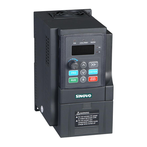
AC DRIVE
User manual
SHENZHEN SINOVO ELECTRIC TECHNOLOGIES CO.,LTD
Add: 5th Floor, No. D Building, Huafeng International Robot Industry Park,
Xixiang Street, Hangcheng Road, Baoan District, Shenzhen City
Tel
: (
0755 29784870
)
Fax: (0755)29784969
Global Service Tel: 400-8818-689
http: www.sinovo-vfd.com
Version: 2.5
Advertisement

Summary of Contents for Sinovo SD90 Series
- Page 1 AC DRIVE User manual SHENZHEN SINOVO ELECTRIC TECHNOLOGIES CO.,LTD Add: 5th Floor, No. D Building, Huafeng International Robot Industry Park, Xixiang Street, Hangcheng Road, Baoan District, Shenzhen City 0755 29784870 Fax: (0755)29784969 Global Service Tel: 400-8818-689 http: www.sinovo-vfd.com Version: 2.5...
-
Page 2: Table Of Contents
Preface Thank you for purchasing the SD90 series AC drive developed by Our company.For the users who use this product for the first time, read the manual carefully. Contents Chapter 1 Safety and Cautions .................2 Chapter 2 Product Information.................9 Chapter 3 Operation And Display..............17 Chapter 4 Function Parameters Table............20... -
Page 3: Chapter 1 Safety And Cautions
Chapter 1 Safety and Cautions Safety and Cautions Definition Read this manual carefully so that you have a thorough understanding. Installation, commissioning or maintenance may be performed in conjunction with this chapter. Our company will assume no ability and responsibility for any injury or loss caused by improper operation. - Page 4 Safety and Cautions Use Stage Safety Grade Precautions Install the equipment on incombustible objects such as metal, and keep it away from combustible materials. Failures to comply may result in a fire. Danger Do not loosen the fixed screws of the components, especially the screws withe red marks.
- Page 5 Safety and Cautions Use Stage Safety Grade Precautions Please confirm the peripheral equipment and cable converter is configured in this manual of the recommended model, all the configuration line in accordance with the connection method of the manual provides the correct wiring. Failure to comply Before will result in accidents.
- Page 6 Safety and Cautions Use Stage Safety Grade Precautions Do not repair or maintain the AC drive at power-on. Failure to comply will result in electric shock. During Ensure that the AC drive is disconnected from all Danger Maint- power suppliers before staring repair or maintenance enance on the AC drive.
- Page 7 Safety and Cautions 1.2.4 Motor heat and noise The output of the AC drive is pulse width modulation (PWM) wave with certain harmonic frequencies, and therefore, the motor temperature, noise, and vibration are slightly greater than those when the AC drive runs at power frequency (50Hz).
- Page 8 Safety and Cautions 1.2.8 The Derating of the AC Drive Different power grade frequency converter has its default carrier frequency, when to run at a higher carrier.frequency, the AC Drive must to reduce the amount when running. 1.2.9 Prohibition of Three-Phase Input Change into Two-Phase Input Do not change the three-phase input of the AC drive into two-phase input.
- Page 9 Safety and Cautions 1.2.14 Adaptable Motor The standard adaptable motor is adaptable four-polo squirrel-cage AC asynchronous induction motor or PMSM. For other types of motor, select a proper AC drive according to the rated motor current. The cooling fan and rotor shaft of general motor are coaxial, which results in reduced cooling effect when the rotational speed declines.
-
Page 10: Chapter 2 Product Information
SD90-2S-0.7G Rated input voltage, frequency and current INPUT: AC1PH 220V 50/60Hz 8.2A Rated output voltage, OUTPUT: AC3PH 220V ~0 600Hz 4.7A frequency and current Bar code S/N: FDLAGCA0A040 SHENZHEN SINOVO ELECTRIC TECHNOLOGIES CO.,LTD. MADE IN CHINA Fig. 2-2 Product nameplate... - Page 11 Product Information 2.3 SD90 Series AC Drive Power Capacity Rated Input Rated Output Adaptable Motor AC Drive Model Current (A) (KW) (KVA) Current (A) Input voltage: single-phase 220V Range:-15%~20% SD90-2S-0.7G 0.75 SD90-2S-1.5G 14.0 23.0 10.0 SD90-2S-2.2G Input voltage: three-phase 380V Range: -15%~20% SD90-4T-0.7G...
- Page 12 Product Information Specifications Item It realizes process-controlled closed loop PID control Onboard PID system easily Simple PLC, 16-speed operating through built-in PLC or control Multi-stage terminal Auto voltage It can keep constant output voltage automatically when regulation (AVR) the mains voltage changes. The current and voltage are limited automatically Overvoltage/ Overcurrent...
- Page 13 Product Information 2.5 Product Outline, Installation Hole Size Fig. 2-4 Outline dimension and installation size Diameter H(mm) W(mm) D(mm) H1(mm) W1(mm) B(mm) GW(kg) Model (mm) Single-phase 220V series SD90-2S-0.7G Ø4 0.90 SD90-2S-1.5G SD90-2S-2.2G Ø5 1.95 Three-phase 380V series SD90-4T-0.7G SD90-4T-1.5G Ø4 0.90 SD90-4T-2.2G...
- Page 14 Product Information 2.6 External Keyboard Dimension 15.00 65+0.3 FUNC FUNC Fig. 2-6 Opening dimension diagram STOP STOP for keypad with base 70.00 1.00 65.00 65+0.3 Fig. 2-5 External Keyboard dimension Fig. 2-7 Opening dimension diagram for keypad without base 2.7 Main Circuit Wiring Diagram Braking resistor Circuit breaker Motor...
- Page 15 Product Information Precautions on the wiring: 1. DC bus have residual voltage after the AC drive is switched off. Ensure voltage is less than 36V before touching the equipment Otherwise, you may get electric shock. 2. Braking resistor connecting terminals: The cable length of the braking resistor shall be less than 5m.
- Page 16 Product Information 2.9 Control circuit terminals and function Type Terminal Function Description Name 10.5V(±3%) Analog input Reference Max output current: 25mA, external potentiometer voltage resistance range is more than 4kΩ 0~20mA: input impedance 500Ω, maximum input Analog current is 25mA input Analog input 0~10V:...
- Page 17 Product Information 2.10 Dial Code Switch Function Description Jumpers Factory default Name Function Figure Rs485 communicational terminal resistance selection 485 (J4) ON: 120Ω terminal connection is valid OFF: without terminal connection I is for current input (0~20mA) Ai1 (J3) 0~10V V is for voltage input (0~10V) I is for current output (0~20mA) AO (J2)
-
Page 18: Chapter 3 Operation And Display
Chapter 3 Operation And Display 3.1 Introduction of the keypad The keypad is used to control inverters, read the state data and adjust parameters. ENTER ENTER Fig 3-1 Keypad Name Instructions LED off means that the AC drive is in the stop state; LED on means the AC drive is in the running state. - Page 19 Operation And Display Name Instructions When the frequency source A or B is set to 1, the setting of the oten- frequency source is determined by analog potentiometer input tiometer voltage. Code Five-figure LED display displays various monitoring date and display alarm code such as set frequency and output frequency.
- Page 20 Operation And Display Parameter display interface Return level 1 menu 50.00 Return ENTER F00.03 F00.04 level 2 menu Return ENTER 50.00 level 3 menu (Modify storage) ENTER Press Modify the parameters Fig.3-2 Operation Procedure of three-level Menu Remarks: You can return to Level II menu from Level III menu by pressing PRG or ENTER.
-
Page 21: Chapter 4 Function Parameters Table
Chapter 4 Function Parameters Table Function Parameters Table The function parameters of the series AC drive have been divided into 14 groups (F00 ~ F0D) according to the function. For the convenience of function codes setting, the function group number corresponds to the first level menu,the function code corresponds to the level 2 menu and the function code corresponds to the level 3 menu. - Page 22 Function Parameters Table Function Setting Range Default Property Name Code Group F00 Basic Function Speed 0: V/F control ◎ F00.00 1: Vector mode 0 control control mode Keypad running command channel (LED OFF) 1: Terminal running command channel ○ F00.01 command (LED ON ) channel...
- Page 23 Function Parameters Table Function Setting Range Property Name Default Code 0: A 1: B Combination mode 2: (A+B) ○ F00.10 of the setting 3: (A-B) 4: Max. (A, B) 5: Min. (A, B) Keypad set ○ 0.00 Hz~F00.03 (max. frequency) F00.11 50.00Hz frequency...
- Page 24 Function Parameters Table Function Setting Range Property Name Default Code ACC and DEC 0: Line ◎ F01.05 mode selection 1: Reserve 0: Decelerate to stop Stop mode ○ F01.06 1: Coast to stop selection Startingfrequency ○ 0.00~F00.03 (Max. frequency) F01.07 0.00Hz of stop braking Waiting time...
- Page 25 Function Parameters Table Function Setting Range Property Name Default Code ○ Start delay time F01.21 0.0~60.0s 0.0s Delay time ○ F01.22 0.0~100.0s 0.0s of the stop speed Group F02 Motor Parameters ● Reserve F02.00 0: General asynchronous motor (With low frequency compensation) ◎...
- Page 26 Function Parameters Table Function Setting Range Property Name Default Code ○ V/F voltage point1 0.0~100.0% (Motor rated voltage) F03.04 00.0% frequency ○ F03.05 F03.03~F03.07 00.00Hz point ○ voltage point 0.0~100.0% (Motor rated voltage) F03.06 00.0% frequency F03.05~F02.05 ○ F03.07 00.00Hz point 3 (Motor rated frequency) ○...
- Page 27 Function Parameters Table Function Setting Range Property Name Default Code Group F04 Input Terminals 0: HDI input enabled (See F04.23~F04.28) 1: AO output enabled (See F04.21) Note: HDI input AO ◎ This function parameter setting F04.00 output function affects the function of the effectivene- selection ss of the control board HDI terminal and AO terminals.
- Page 28 Function Parameters Table Function Setting Range Property Name Default Code 26: Reserve 27: Reserve 28: Counter reset S5 terminal ◎ 29: Reserve F04.05 function selection 30: ACC/DEC prohibited 31: Reserve 32: Reserve 33:Frequency setting clear 34: DC braking 35: Reserve 36: Shift the command to the keypad ●...
- Page 29 Function Parameters Table Function Setting Range Property Name Default Code witch-off delay ○ F04.16 0.000~50.000s 0.000s of 3 terminal witch-on delay ○ F04.17 0.000~50.000s 0.000s of 4 terminal witch-off delay ○ F04.18 0.000~50.000s 0.000s of 4 terminal witch-on delay ○ F04.19 0.000~50.000s 0.000s...
- Page 30 Function Parameters Table Function Setting Range Property Name Default Code input filter ○ F04.33 0.000~10.000s 0.100s time Keypad analog ○ F04.34 0.000~10.000s 0.050s filter time Group F05 Output Terminals ● F05.00 Reserve 0: Invalid 1: Running ○ 2: Forward running Y output F05.01 3: Reverse running...
- Page 31 Function Parameters Table Function Setting Range Property Name Default Code Relay switch- ○ F05.09 0.000~50.000s 0.000s off delay time 0: Running frequency 1: Set frequency 2: Ramp reference frequency 3: Running speed 4: Output current (relative to AC drive rated current) 5: Output current (relative to motor rated current) 6: Output voltage...
- Page 32 Function Parameters Table Function Setting Range Property Name Default Code ------ – F06.02 Reserved 0: Only valid for keypad control 1: Both valid for keypad and STOP/RESET terminal control ○ F06.03 stop function 2: Both valid for keypad and selection communication control 3: Valid for all control modes 0x0000~0xFFFF...
- Page 33 Function Parameters Table Function Setting Range Property Name Default Code 0x000~0x7FF Bit0: Set frequency (Hz is flicking slowly) Bit1: Bus voltage Bit2: Input terminal state Bit3: Output terminal state Bit4: PID reference value Parameters for Bit5: PID feedback value ○ F06.06 0x0FF stopping state...
- Page 34 Function Parameters Table Function Setting Range Property Name Default Code ● Current fault type F06.18 Previous 1 ● F06.19 See Chapter Common fault type Faults and Solutions Previous 2 ● F06.20 fault type Running frequency ● —— F06.21 0.00Hz at current fault Ramp reference ●...
- Page 35 Function Parameters Table Function Setting Range Property Name Default Code Input terminals ● —— F06.35 state at previous fault Output terminals ● —— F06.36 state at previous fault Group F07 Enhanced Group Model Acceleration ○ F07.00 0.0~3600.0s dependent time 2 Model Deceleration ○...
- Page 36 Function Parameters Table Function Setting Range Property Name Default Code Frequency arrival ○ 0.0~F00.03 (Max. frequency ) F07.17 0.00Hz detection value Energy 0: Energy braking disable ○ F07.18 braking enable 1: Energy braking enable 220V level: Threshold 380.0V ○ voltage of F07.19 200.0~1000.0V 380V level:...
- Page 37 Function Parameters Table Function Setting Range Property Name Default Code UP/DOWN 1: Valid in running, clear after stop ○ terminal control 2: Valid in running, clear after F07.24 0x000 setting receiving the stop commands Up terminal ○ frequency F07.25 0.01~50.00s 0.50s changing ratio DOWN terminal...
- Page 38 Function Parameters Table Function Setting Range Property Name Default Code ntegral time1 ○ F08.05 0.00~10.00s 0.20s (Ti 1) Differential time ○ F08.06 0.00~10.00s 0.00s (Td 1) Sampling cycle ○ F08.07 0.01~100.00s 0.10s PID control ○ F08.08 0.0~100.0% 0.0% deviation limit F08.10~100.0% Output upper ○...
- Page 39 Function Parameters Table Function Setting Range Property Name Default Code Input deviation ○ threshold when F08.18 0.0~100.00% PID switching ○ F08.19 PID initial value -100.0%~100.0% 0.0% PID initial ○ F08.20 0.0~600.0s 0.0s holding time Group F09 Fixed - length , Count and Fixed Time Parameters ●...
- Page 40 Function Parameters Table Function Setting Range Property Name Default Code The running time ○ 0.0~6553.5s(min) F0A.03 0.0s of step 0 ○ Multi-stage speed 1 F0A.04 -100.0~100.0% 0.0% The running time ○ 0.0~6553.5s(min) F0A.05 0.0s of step 1 ○ Multi-stage speed 2 F0A.06 -100.0~100.0% 0.0%...
- Page 41 Function Parameters Table Function Setting Range Property Name Default Code ○ Multi-stage speed11 F0A.24 -100.0~100.0% 0.0% The running time ○ 0.0~6553.5s(min) F0A.25 0.0s of step 11 ○ Multi-stage speed12 F0A.26 -100.0~100.0% 0.0% The running time ○ 0.0~6553.5s(min) F0A.27 0.0s of step 12 ○...
- Page 42 Function Parameters Table Function Setting Range Property Name Default Code 120~150% 120% Voltage (Standard bus voltage 220V) ○ protection of F0B.04 120~150% over-voltage stall 125% (Standard bus voltage 380V) 0: Current-limiting is invalid Current limit ◎ F0B.05 1: Current-limiting is valid action selection Model Automatic current...
- Page 43 Function Parameters Table Function Setting Range Property Name Default Code Fault time of ○ 0.0 (invalid), 0.1~60.0s F0C.04 communication 0.0s overtime 0: Alarm and stop freely 1: No alarm and continue to run 2: No alarm and stop according to the Transmission ○...
- Page 44 Function Parameters Table Function Setting Range Property Name Default Code ● DC bus voltage F0D.11 0.0~2000.0V Digital input ● F0D.12 0x00~0x1F terminals state Digital output ● F0D.13 terminals state ● Digital adjustment F0D.14 0.00Hz~F00.03 0.00Hz ● F0D.15 Reserve ● Linear speed F0D.16 0~65535 ●...
-
Page 45: Chapter 5 Troubleshooting
Chapter 5 Troubleshooting Danger ª Only qualified electricians are allowed to maintain the AC drive. Read the safety instruction in chapter safety precaution before working on the AC drive. 5.1 Fault Code List Fault Type No Fault Code Possible Causes Solutions Accelerating ◆... - Page 46 Troubleshooting Fault Type No Fault Code Possible Causes Solutions ◆ The acceleration is too short; ◆ Increase the acceleration ◆ Reset the rotating motor; time; ◆ The voltage of power ◆ Avoid restart after stopping; supply is too low; ◆ Check the power of the The AC drive E.oL2...
- Page 47 Troubleshooting Fault Type No Fault Code Possible Causes Solutions ◆ Braking circuit fault or ◆ Check the braking unit and Braking unit damage to the brake pipes; replace the braking pipe; E.BrE fault ◆ External braking resistor ◆ Increase the braking resistor. is not sufficient.
- Page 48 Troubleshooting Fault Possible Causes Solutions Power ON AC Drive ◆ The cooling fan is damaged or displaynormal, locked-rotor occurs; ◆ Replace the damaged fan; after runningshow P.oFF and quickly ◆ The peripheral control terminal cable ◆ Eliminate external short extinguishOff, is short circuited.
-
Page 49: Chapter 6 Rss485 Communication Protocol
Chapter 6 Rs485 Communication Protocol 6.1 Function Protocol Read data: Slave responding frame 1.Read a single or multiple data(0x03) ADDR ADDR 0x03 0x03 Byte number N*2 High bit of the start High bit of data 1 Low bit of the start Low bit of data 1 High bit of data number ……... - Page 50 Rs485 Communication protocol 4 Error message response Sometimes, errors occurs during the process of the communication. For example, reading or writing data to an illegal address, etc., then the slave will not work as a normal read-write response to reply the host, but send a wrong message frame.
- Page 51 Rs485 Communication protocol 6.2 Communication Parameter Address MODBUS communication includes read and write operations of function parameters and some special register’s read and write operations. Special register includes control register, set registers, state registers, and factory information. (1) The Definition of Communication Parameter Address The function code number and parameter label is the representation rule of the parameter address.
- Page 52 Rs485 Communication protocol For example: The parameter F04.13 is stored in EEPROM , and the address is represented as 0xF40D; The parameter F04.13 is not stored in the EEPROM, and the address is represented as 0x040D; Read of both EEPROM address and RAM address are valid. When read the function code parameters, user can only read the maximum of 16 consecutive address parameters.more than 16, the AC drive will return the illegal data.
- Page 53 Rs485 Communication protocol Register Setup description Function Bit0:=0 invalid; =1 Forward running Bit1:=0 invalid; =1 Reverse running bit2:=0 invalid; =1 Forward jog Bit3:=0 invalid; =1 Reverse jog Control Control Bit4:=0 invalid; =1 Deceleration stop 2001H Register Bit register Bit5:=0 invalid; =1 Free stop Bit6:=0 invalid;...
Need help?
Do you have a question about the SD90 Series and is the answer not in the manual?
Questions and answers