Advertisement
Quick Links
Implements Pty Ltd
AGRICULTURAL ENGINEERS
OPERATOR'S MANUAL
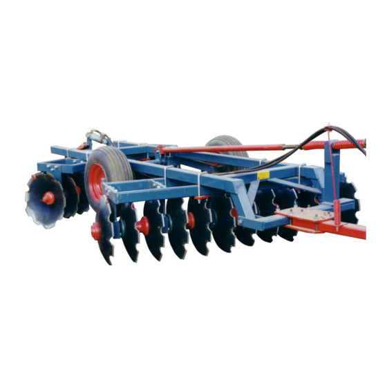
RM 80 TRAILING OFFSET DISC CULTIVATOR
PRODUCT NO.
0850/0860/0870
0851/0861/0871
0852/0862/0872
0853/0863/0873
130 FRANKSTON-DANDENONG RD, DANDENONG SOUTH, VIC. 3175 AUSTRALIA
PHONE (03) 9791 2494
berends@johnberendsimplements.com.au
John Berends
PARTS LIST
20 Plate with 24" x 5mm/24" x 6mm/26" x 6mm Discs
24 Plate with 24" x 5mm/24" x 6mm/26" x 6mm Discs
28 Plate with 24" x 5mm/24" x 6mm/26" x 6mm Discs
32 Plate with 24" x 5mm/24" x 6mm/26" x 6mm Discs
(ABN 79 007 035 369)
FAX NO. (03) 9794 5568
www.johnberendsimplements.com.au
Advertisement

Summary of Contents for John Berends Implements RM 80
- Page 1 John Berends Implements Pty Ltd AGRICULTURAL ENGINEERS OPERATOR’S MANUAL PARTS LIST RM 80 TRAILING OFFSET DISC CULTIVATOR PRODUCT NO. 0850/0860/0870 20 Plate with 24” x 5mm/24” x 6mm/26” x 6mm Discs 0851/0861/0871 24 Plate with 24” x 5mm/24” x 6mm/26” x 6mm Discs 0852/0862/0872 28 Plate with 24”...
-
Page 2: Table Of Contents
TABLE OF CONTENTS Page No. SAFETY INSTRUCTIONS..................3 INTRODUCTION………………………………………………………………………….5 SAFETY FEATURES....................6 ASSEMBLY......................7 OPERATION......................9 MAINTENANCE.......................11 SPARE PARTS......................12 DISC SET-UP……………………………………………………………………………...16... -
Page 3: Safety Instructions
SAFETY Farm machinery is dangerous if operated incorrectly so please read this manual in its entirety prior to operating the machine. No operator, however experienced in farm machinery operation, should attempt to use any machine they have not been competently trained to use. Your local Department of Agriculture can help you with training, as can most Occupational Health and Safety offices, Agricultural schools and colleges and farm equipment dealerships. - Page 4 After striking a foreign object or if there are doubts about the performance of the machine, stop the tractor as described and check if machine is making excessive noise. Extreme caution must be taken when working in public areas (roadsides etc). It is recommended that flaps and chains are fitted to slashers when operating in public areas.
-
Page 5: Introduction
RM80 Trailing Offset Disc Cultivators Gibbins Rawling have been making ploughs since 1878 - over 100 years of experience! The RM 80 offset disc cultivating plough is designed for extremely tough Australian conditions. It is similar to the RM75 with the main difference being in the greater number of bearings and shorter axles in the disc gang assemblies. -
Page 6: Safety Features
Safety Features 1. SERIAL NUMBER (Decal – inside frame) 2. WARNING DECAL 3. BERENDS DECAL (Top of frame) -
Page 7: Assembly
MACHINE ASSEMBLY GANG ASEMBLY CAUTION: Due to the size and awkward nature of the trailing discs it is important that all components are adequately supported. As there are a number of sizes of discs available, refer to the attached set-up sheet on the back page in this manual. - Page 8 WHEEL ASSEMBLY Position the axle (less the wheels) underneath the main frame between the two gangs. The two arms of the axle should be facing forward with the main shaft at the rear. The axle lug (transport lug), which later connects to the hydraulic ram, should be on the right side of the machine when facing the direction of travel.
-
Page 9: Operation
HYDRAULIC RAM AND HOSES Attach the main body section of the hydraulic cylinder to the bottom hole of the transport lug on the main frame. Connect the extending rod end of the cylinder to the bottom hole of the transport lug located on the wheel axle. Secure with clevis pins and clips. Attach the hydraulic hoses to the ram and fit couplings to the other end of the hoses. - Page 10 it may be necessary to shift both gangs across so as to transfer the weight away from the side dipping in. Wheel set-up There are a couple of points regarding the setting of the wheel for depth. If the wheels are right in the air whilst cultivating, all the weight of the frame bears on the gang frames.
-
Page 11: Maintenance
MAINTENANCE When doing any type of maintenance on this machine, always follow the safety steps described in this manual. Use only authorised genuine parts for replacement. The cultivator must be adequately supported under its body (Make certain it cannot fall). Bolts, Nuts and Bronze Bushes Keep all bolts tight, in particular gang bolts. -
Page 12: Spare Parts
Glossary of terms c/w = Complete with sw = Spring Washer n.s.s. = Not serviced separately a.r. = As required fw = Flat Washer RM 80 Top Frame Key No Part No Quantity Description 1564 Main Frame 3375 ‘U’... - Page 13 RM 80 Top Frame 16 & 17 14 & 15 22 & 23...
- Page 14 RM 80 Gang Assembly Key No Part No Quantity Description 1581 Gang Frame 3332 C.163 – 3 disc gang bolt axle 3333 C.164 – 4 disc gang bolt axle 3334 C.165 – 5 disc gang bolt axle 3345 1 per axle...
- Page 15 RM 80 Wheel Assembly Key No Part No Quantity Description 3360 Transport bar 3361 Pin suit transport bar 1940 Linch pin 3362 Seal suit FAD hub 3363 Inner bearing & cup suit FAD hub 3365 Hub, FAD 3364 Stud suit FAD hub 3366 Outer bearing &...
-
Page 16: Disc Set-Up
280mm 370mm 685mm 570mm 200mm Model 20 PLATE 115mm 610mm 305mm 420mm 535mm 180mm 330mm 380mm 24 PLATE 350mm 845mm 540mm 655mm 770mm 415mm 565mm 615mm 28 PLATE 585mm 1080mm 775mm 890mm 1005mm 650mm 800mm 850mm 32 PLATE 820mm 1315mm 1010mm 1125mm 1240mm...
Need help?
Do you have a question about the RM 80 and is the answer not in the manual?
Questions and answers