Table of Contents
Advertisement
Available languages
Available languages
Quick Links
Advertisement
Chapters
Table of Contents

Related Manuals for eQ-3 HomeMatic HMW-Sys-OP-DR

Summary of Contents for eQ-3 HomeMatic HMW-Sys-OP-DR
- Page 1 Installations- und Bedienungsanleitung (S. 4) Installation and operating manual (p. 18) Überspannungsschutz für 24V und RS485 mit Busabschluss-Widerstand Hutschienenmontage: Overvoltage protection for 24V and RS485 with bus terminator for mounting on DIN rails: HMW-Sys-OP-DR...
- Page 2 1. Ausgabe Deutsch 06/2009 Dokumentation © 2009 eQ-3 Ltd., Hong Kong Alle Rechte vorbehalten. Ohne schriftliche Zustim- mung des Herausgebers darf dieses Handbuch auch nicht auszugsweise in irgendeiner Form reproduziert werden oder unter Verwendung elektronischer, me- chanischer oder chemischer Verfahren vervielfältigt oder verarbeitet werden.
-
Page 3: Table Of Contents
Inhaltsverzeichnis Hinweise zu dieser Anleitung ... . . 4 Gefahrenhinweise ..... . 4 Funktion . -
Page 4: Hinweise Zu Dieser Anleitung
Hinweise zu dieser Anleitung Lesen Sie diese Anleitung sorgfältig, bevor Sie ihre HomeMatic-Komponenten in Betrieb nehmen. Bewahren Sie die Anleitung zum späteren Nach- schlagen auf! Wenn Sie das Gerät anderen Personen zur Nutzung überlassen, übergeben Sie auch diese Bedienungs- anleitung. Benutzte Symbole: Achtung! Hier wird auf eine Gefahr hinge- wiesen. - Page 5 Der Betrieb des Gerätes ist ausschließlich mit einer Gleichspannung von 24 V zulässig. Arbeiten in Installationsbereichen mit Netzspannung dürfen nur durch eine Elektro-Fachkraft (nach VDE 0100) erfolgen. Dabei sind die geltenden Unfallverhü- tungsvorschriften zu beachten. Bei Nichtbeachtung der Installationshinweise kön- nen Brand- oder andere Gefahren entstehen.
-
Page 6: Funktion
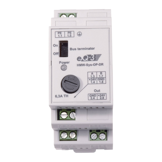
Funktion Der auf einer DIN-Hutschiene innerhalb einer Vertei- lung zu installierende Überspannungsschutz schützt nachgeschaltete 24-V-Geräte wie z. B. HomeMatic- Komponenten, vor transienten Überspannungen, d.h, hochenergetischen Überspannungen, wie sie durch Blitzeinschläge, elektrostatische Entladungen, Schalthandlungen u.ä. in Stromverteilnetzen entste- hen können. Dazu wird die vom Systemnetzteil kommende 24-V- Spannung durch den Überspannungsschutz geleitet. - Page 7 (A) – PE-Anschluss (B) – Schalter für Busabschluss (C) – Geräte-LED (D) – Ausschaltsicherung (E) – Busanschluss A (F) – Busanschluss B (G) – +24 V vom Netzteil (H) – GND vom Netzteil (I) – GND zum zu schützenden Gerät (J) –...
-
Page 8: Allgemeine Systeminformation Zu Homematic
4 Allgemeine Systeminformation zu HomeMatic Dieses Gerät ist Teil des HomeMatic-Haussteuersy- stems. Weitere Anschlusshilfen entnehmen Sie bitte dem HomeMatic Systemhandbuch. Alle technischen Dokumente und Updates finden Sie stets aktuell unter www.HomeMatic.com. Allgemeine Hinweise Installation/Bussystem 5.1 Allgemeine Hinweise zur Installation Grundsätzlich kann man die Anschlüsse der HMW-Komponenten in zwei Gruppen einteilen. -
Page 9: Topologie Des Bussystems
empfiehlt sich die Verwendung einer Fernmelde- Installationsleitung oder vergleichbarer Steuerleitung. Zu beachten ist allerdings, dass diese Leitungen generell getrennt von jeglichen 230-V-führenden Leitungen, entsprechend den VDE-Richtlinien, zu ver- legen sind. Dabei ist ein Mindestabstand von 8 mm zwischen beiden Leitungsarten zu beachten. Beim Anschluss des RS485-Busses sind die A-Klemmen (1.3), die B-Klemmen (1.7), die 24-V-Spannungs versorgung und die Masseklemmen... - Page 10 Es ist auf jeden Fall zu empfehlen, auf jeder Etage mindestens eine Unterverteilung zu installieren. Bei größeren Gebäuden kann es auch sinnvoll sein, mehrere Verteilungen pro Etage (z. B. separat für jeden Flur) vorzusehen. Entsprechend sind alle Last- und Steuerleitungen sternförmig zu den entspre- chenden Unterverteilungen zu führen.
-
Page 11: Installation
Installation Beachten Sie die Installationsvorschriften für Installationen in Verteilersystemen und für Blitzschutz- und Potentialausgleichssysteme. Setzen Sie das Hutschienengerät auf die Hutschiene auf und verriegeln Sie es. Achten Sie dabei darauf, dass die Rastfeder kom- plett einrastet und das Gerät fest auf der Schiene sitzt. - Page 12 Mindestabstand zwischen Bus-/ Stromversor- gungsleitungen und netzspan- nungführenden Leitungen 8 mm!
- Page 13 Verdrahten Sie zuerst die Verbindung zur PEN- (Schutzleiter) Stromschiene in der Verteilung sowie zur Potentialausgleichschiene, die mit dem Funda- menterder verbunden ist. Beachten Sie dabei die folgenden Hinweise: Ausführung der Verdrahtung nach den Vor- schriften für Blitzschutz und Überspannungs- schutzgeräte lt. VDE 0100 Verdrahtung nur mit normgerechter, starrer PEN-Leitung (grün-gelb) mit einem Querschnitt von 2,5 mm...
-
Page 14: Betrieb/Sicherungswechsel
Dabei spielt der Standort des Gerätes im Bus keine Rolle. Es ist zu beachten, dass je RS485-Bus nur ein Bus- abschluss installiert/aktiviert werden darf. Ist bereits ein Busabschluss installiert, ist der Schalter „Bus terminator” auf „OFF” zu stellen! Betrieb/Sicherungswechsel Beachten Sie bei der Anzahl der anzuschlie- ßenden Geräte, dass deren Gesamtstromauf- nahme 5 A nicht überschreiben darf! Nach Zuschalten der Spannungsversorgung leuchtet... -
Page 15: Wartung Und Reinigung
Treten infolge einer Überspannung zu hohe Begrenzungsströme auf, so spricht die integrierte Sicherung des Gerätes an, die Kontroll-Leuchte „Power” verlischt. Schalten Sie in diesem Fall den Netzanschluss des Netzgerätes ab und wechseln Sie die Sicherung gegen eine Sicherung gleicher Auslösestromstärke und gleichen Typs aus: - Glasrohrsicherung 5 x 20 mm, 6,3 A / 250 V TH - Das Herausdrehen der Sicherungsfassung erfolgt... -
Page 16: Technische Daten
Technische Daten RS485-Busabschluss: schaltbar EMV-Schutz-Zone: 1/2/3 (ab Hauptverteiler) Belastung 24 V-Ausgang: max. 5 A Nenn-Ableit-Stoßstrom: 24-V-Schutz: 10 kA @ 90 V 1 kA @ 38 V 1 mA @ 29 V RS485-Bus-Schutz: 28 A @ 21 V 1 mA @ 15 V Ruhestrom: 10 mA Zugelassene... - Page 17 Entsorgungshinweis: Gerät nicht im Hausmüll entsorgen! Elektro- nische Geräte sind entsprechend der Richt- linie über Elektro- und Elektronik-Altgeräte über die örtlichen Sammelstellen für Elektronik-Alt- geräte zu entsorgen. Das CE-Zeichen ist ein Freiverkehrszeichen, das sich ausschließlich an die Behörden wendet und keine Zusicherung von Eigenschaften beinhaltet.
- Page 18 English edition 07/2009 Documentation © 2009 eQ-3 Ltd., Hong Kong All rights reserved. This manual may not be reprodu- ced in any format, either in whole or in part, nor may it be duplicated or edited by electronic, mechanical or chemical means, without the written consent of the publisher.
- Page 19 Table of contents Information about this manual ... 20 Hazard information ....20 Function .
-
Page 20: Information About This Manual
Information about this manual Read this manual carefully before starting to use your HomeMatic components. Keep the manual so you can refer to it at a later date should you need to. If you hand over the device to other persons for use, please hand over the operating manual as well. - Page 21 The device must only be operated using a 24 V DC voltage. Only qualified electricians (to VDE 0100) are per- mitted to carry out work in installation areas where mains voltage is present. Applicable accident pre- vention regulations must be complied with whilst such work is being carried out.
-
Page 22: Function
Function The surge protector, to be installed on a DIN rail within a distribution board, protects downstream 24 V devices, such as HomeMatic components, from transient overvoltages, that is from the high-energy overvoltages that can occur in current distribution systems as a result of lightning strikes, electrostatic discharge, switching operations or similar. - Page 23 (A) – PE connection (B) – Switch for bus terminator (C) – Device LED (D) – Disconnecting fuse (E) – Bus connection A (F) – Bus connection B (G) – +24 V from power supply unit (H) – GND from power supply unit (I) –...
-
Page 24: General Information About The Homematic System
General information about the HomeMatic system This device is part of the HomeMatic home control system. For additional connection information, please refer to the HomeMatic system manual. You can find the latest versions of all technical documents and the latest updates at www.HomeMatic.com. -
Page 25: Topology Of The Bus System
have to be used. Using interior telecommunications wiring or comparable control wiring is recommended. Make sure, however, that the wires of the load and the control side are separated conforming with VDE regulations within the sub-distribution. Keep a minimum spacing of 8 mm between the two types of wiring. - Page 26 However, we do recommend that at least one sub- distribution board is always installed on each floor. For larger buildings it may make more sense to provide se- veral distribution boards on every floor (a separate one for each corridor, for example). Accordingly, all load and control cables must be routed to the correspon- ding sub-distribution boards in a star configuration.
-
Page 27: Installation
Installation Refer to the relevant installation regulations when performing installations in distribution systems and to the regulations pertaining to lightning protection and equipotential bonding systems. Place the DIN rail-mounting device onto the DIN rail and lock it in position. Make sure that the locating springs engage properly and that the device is securely seated on the rail. - Page 28 Equipotential bonding strip A minimum spacing of 8 mm must be observed between the bus/power supply cables and the cables carrying mains voltage. Protected Power voltage supply output unit...
- Page 29 First of all, wire the connection to the PEN (protec- tive conductor) busbar in the distribution board and to the equipotential bonding strip that is connected to the foundation earth. When doing so, observe the following notes: Configure the wiring in accordance with the regulations pertaining to lightning protection and surge protectors contained in VDE 0100.
-
Page 30: Operation/Replacing The Fuse
The location of the device in the bus does not make any difference here. Please note that only one bus terminator may be installed/activated for each RS485 bus. If a bus terminator is already installed, the “Bus terminator” switch must be set to “OFF”. Operation/Replacing the fuse Please note that the total power consumed by all the devices to be connected must not... -
Page 31: Maintenance And Cleaning
If an overvoltage causes excessively high restricted currents to occur, the fuse integrated in the device trips and the “Power” indicator light goes out. If this happens, switch the mains connection to the power supply unit off and replace the fuse with one of the same tripping current and the same type: - Glass tube fuse 5 x 20 mm, 6.3 A/250 V TH –... -
Page 32: Technical Specifications
Technical specifications RRS485 bus terminator: Switchable EMC protection zone: 1/2/3 (from main distributi- on board) Load at 24 V output: Max. 5 A Rated discharge current: 24 V protection: 10 kA @ 90 V 1 kA @ 38 V 1 mA @ 29 V RS485 bus protection: 28 A @ 21 V 1 mA @ 15 V... - Page 33 Instructions for disposal: Do not dispose of the device with regular do- mestic waste. Electronic equipment must be disposed of at local collection points for waste electronic equipment in compliance with the Waste Electrical and Electronic Equipment Directive. The CE Marking is simply an official symbol relating to the free movement of a product;...
- Page 36 AG Maiburger Straße 29 D-26789 Leer www.eQ-3.com...
Need help?
Do you have a question about the HomeMatic HMW-Sys-OP-DR and is the answer not in the manual?
Questions and answers