
Summary of Contents for Bossard RTB-20
- Page 1 Operating instructions Battery-Blind-Riveting-Tool RTB-20(-S) NOTE In case of doubt, the original German version of the operating instructions applies.
-
Page 2: Table Of Contents
Table of contents 1 Operating principles Scope of delivery General information Signs and symbols used Structure of the warnings Technical terms and abbreviations used Intended use Improper use Duties of the operator Duties of personnel 1.10 Training of personnel 1.11 Guarantee and liability 1.12 Copyright... - Page 3 4.2.15 Charge state of the battery Display 4.3.1 Display notifications Bossard SmartTool-Manager 4.4.1 Setup 4.4.2 General → Process control 4.4.3 General → Energy & Lighting 4.4.4 General → Features 4.4.5 General → TM version 4.4.6 Management 4.4.7 Signals → OLED-display 4.4.8...
-
Page 4: Operating Principles
1 Operating principles Dear customers, thank you for choosing a Bossard SmartTool product. This quality product „Made in Germany“ fulfils the highest requirements with regard to performance, quality and accuracy. When used correctly the product will undoubtedly perform very well for many years. - Page 5 This operating instructions must be read and applied by every person who is assigned to conduct work using this tool. In addition to this operating instructions the applicable regulations on accident prevention and environmental protection should be observed. NOTE After reading, keep the operating instructions in a place accessible to every operator.
-
Page 6: Signs And Symbols Used
Signs and symbols used The following signs and symbols will be used in this operating instructions or on the product: Symbol Explanation Read this operating instructions Do not dispose with household waste Do not dispose the battery in a fire Do not throw the battery into water EU conformity marking ®... -
Page 7: Structure Of The Warnings
Structure of the warnings The warnings are structured as follows: DANGER Indicates an immediate dangerous situation that can lead to serious or even deadly injuries and/or that could seriously damage or even destroy the tool. WARNING Indicates a potentially dangerous situation that can lead to serious injuries and/or damage to the tool. -
Page 8: Intended Use
• following all indications of the operating instructions and • observance of inspection and maintenance works. Any other use or use beyond that is considered improper use. Neighter HS-Technik GmbH as manufacturer nor Bossard AG as sales partner are liable for any resulting damage. Improper use DANGER The use of this tool for other purposes, e.g. -
Page 9: Duties Of The Operator
Duties of the operator The operator undertakes to only allow people who are familiar with the basic regulations on occupational safety and accident prevention and who have been trained on how to use the tool at the workplace to work with this tool. The safety awareness of the personnel while working has to be reviewed at regular intervals. -
Page 10: Training Of Personnel
1.10 Training of personnel Only trained and instructed personnel should work with this tool. The responsibilities of the personnel must be clearly defined. Trainees may only work with this power tool under the supervision of an experienced person. 1.11 Guarantee and liability Guarantee and liability claims for personal injury and property damage are excluded, if caused by one or more of the following: •... -
Page 11: Copyright
They contain guidelines and information which may not be fully, or partially • reproduced • distributed or • otherwise shared. The copyright of these operating instructions is retained by HS-Technik GmbH / Bossard AG. Address of the manufacturer: Address of the distributor: Bossard AG HS-Technik GmbH... -
Page 12: General Safety Information For Power Tools
NOTE Only have your device repaired by qualified professional staff and only with original replacement parts which are available at Bossard. This ensures that the safety of the device is maintained. The term „power tool” used in the safety information refers to mains-operated power tools (with mains cable) and to battery-operated power tools (without mains cable). -
Page 13: Electrical Safety
Electrical safety a) Avoid body contact with grounded surfaces such as pipes, heaters, stoves and refrig- erators. There is an increased risk of electric shock if your body is grounded. b) Keep power tools away from rain or moisture. Penetration of water into a power tool increases the risk of electric shock. -
Page 14: Use And Handling Of Power Tools
e) Wear suitable clothing. Do not wear loose clothing or jewellery. Keep hair and cloth- ing away from moving parts. Loose clothing, jewellery or long hair can get caught in moving parts. f) Do not lull yourself into a false sense of security and do not disregard the safety rules for power tools, even if you are familiar with the power tool after repeated use. -
Page 15: Use And Handling Of Battery Tools
h) Keep handles and gripping surfaces dry, clean and free of oil and grease. Slippery handles and gripping surfaces do not allow safe operation and control of the power tool in unforeseen situations. i) Use the correct power tool. Do not use under-performing tools for heavy loads. Do not use tools for purposes and work for which they are not intended. -
Page 16: Service
g) Follow all instructions for charging and never charge the battery or the battery tool outside of the temperature range specified in the operating instructions. Incorrect charging or charging outside of the approved temperature range can damage the bat- tery and increase the risk of fire. Service a) Only have your power tool repaired by qualified professional staff and only with orig- inal replacement parts which can be available at HS Technik GmbH. -
Page 17: Important Information About This Tool
3 Important information about this tool Handling the associated lithium ion battery a) Observe the operating instructions of the Li-Ion battery. b) If the battery will not be used over a longer period of time it may not remain on the charger or on the machine. -
Page 18: Information On The Associated Charger
Information on the associated charger a) Observe the operating instructions of the charger. b) The charger may not be connected to a step-up converter, generator or a direct current outlet. c) Ensure that the ventilation slots on the charger are not covered or blocked. d) Never charge the battery inside a carton or a closed container. -
Page 19: Cleaning The Device And Disposal
Cleaning the device and disposal Substances and materials used must be handled and disposed of properly, particularly when cleaning with solvents. Do not throw the used battery into the household waste, fire or water, instead have it professional disposed of by a specialist or the manufacturer. - 19 -... -
Page 20: Start-Up And Use
4 Start-up and use DANGER Risk of injury from damaged tools Damaged tools can lead to injuries or damages. • All damaged parts must be repaired before use. Risk of injury from falling tools Falling tools can lead to injuries or damages. •... -
Page 21: Tool Structure
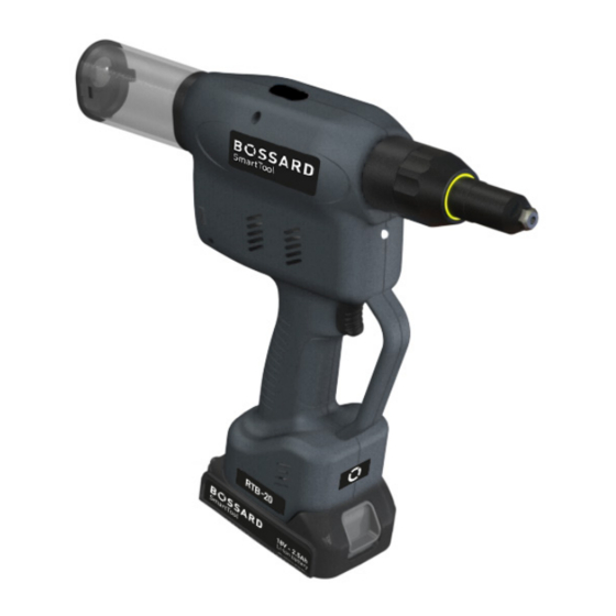
Tool structure 1. Start button 2. Traction head with nose piece* 3. Riveting mandrel container 4. Multi-colour LED 5. 18 V Li-ion battery* 6. OLED Display 7. LED for work area lighting * Battery, nose piece and threaded mandrel are not included in the standard scope of delivery and must be ordered separately. -
Page 22: Operation
Operation 4.2.1 Inserting and removing the battery • In order to insert the battery (1), align it so that it can be easily pushed onto the mount- ing provided along the plastic guide. After sliding it on completely, the fastening clip (2) must lock the battery firmly and properly into place in the tool housing. -
Page 23: Press Start Button
4.2.2 Press start button Pressing or actuating the start button starts or stops the tool. NOTE The battery riveting tool only starts when the battery has sufficient capacity. * Start button 4.2.3 Front LED WARNING Risk of injury from the light emitting diode Looking directly into the light emitting diode can lead to eye injuries. -
Page 24: Led Indicator At The Back And Sound Signals
4.2.4 LED indicator at the back and sound signals Circumferential indicator lights up green after setting, no sound signal • The parametrised setting was completed successfully. • The battery capacity is sufficient, the tool is ready for the next setting. Circumferential indicator lights red after setting, no sound signal •... -
Page 25: Empty Remaining Collection Container
4.2.6 Empty remaining collection container The riveting mandrel container for the torn off riveting mandrels must be emptied regularly. Turn the container by hand approx. 45° „counter clockwise“ or „clockwise“ in order to loosen it and remove it from the riveting machine. In order to place the riveting mandrel container back on after emptying align the noses and turn the riveting mandrel container approx. - Page 26 DANGER Risk of injury from projecting rivets Injuries can result if you do not use the original, undamaged riveting mandrel container • Always use only the original, undamaged riveting mandrel container • Ensure that the container is correctly installed (fully latched locking mechanism) In order to prevent use of the tool without a riveting mandrel container the riveting mandrel container is monitored using a sensor.
-
Page 27: Reducing Pipes
4.2.7 Reducing pipes We provide suitable reducing pipes for rivets with a mandrel diameter smaller than 4.0 mm. Reducing pipes reduce the diameter of the guide tube through the tool and thereby prevent the remaining rivet mandrel from jamming in the guide tube. Reducer Item number Tool type... -
Page 28: Selection Of Nose Assembly
Use a 12 mm and 14 mm wrench size tool for mounting the nose piece. 4.2.9 Selection of nose assembly Tool type Fastener Compatible traction head BST-RTB-EX-1* Expander (040 – 060) BST-RTB-EX-2* Expander (070 – 100) BST-RTB-HUCK up to 6,3 mm mandrel diameter Huck / Arconic / Howmet / Gage Bilt** BST-RTB-Cherry up to 6,3 mm mandrel diameter Cherry Aerospace partially Huck / Arconic / Howmet / Gage Bilt** * Incl. -
Page 29: Set Fastener
4.2.10 Set fastener NOTE Always place the riveting tool at a right angle (90°) to the work surface to be riveted. An oblique placement leads to faulty riveting. Use only appropriate nose pieces for the rivet. An incorrect nose piece can lead to damages in the clamping jaws as well as the nose piece. -
Page 30: Contact Pressure Sensor
4.2.11 Contact pressure sensor The pressure trigger ensures that the blind rivet can only be processed if the pressure trigger is activated. This prevents accidental triggering and ensures that the parts to be processed are lying next to each other. The pressure trigger can be deactivated in the SmartTool-Manager as described below. -
Page 31: Quickriv-Technology
The pressure trigger can not be used in the following tool types due to the system: • BST-RTB-EX-1 • BST-RTB-EX-2 • BST-RTB-HUCK • BST-RTB-Cherry 4.2.12 QuickRiv-Technology The tool has a monitor which automatically recognises when the rivet mandrel breaks and returns the tool back into the starting position. Depending on the traction head or fastener, the break detection must be deactivated. -
Page 32: Overload
4.2.13 Overload In order to avoid damages as a result of excess temperatures during continuous operation it is important to observe sufficient break times during the installation process. If the tool should go into an automatic shut-down (TEMP FET) STOP as a result of excess temperatures the break times should be reviewed and adjusted. -
Page 33: Charge State Of The Battery
4.2.15 Charge state of the battery NOTE The tool will only start if the battery has sufficient charge capacity. When fully charged, the battery will display the charge state on the display on the left side as a green battery symbol. As the battery voltage decreases the colour of the sym- bol will change to yellow and then red. -
Page 34: Display
Display The displays can be adapted in the SmartTool-Manager so that the worker is shown, for example, exact values for riveting, stroke, only one OK or NOK, or the counting process. The displays can be shown in German or English. You can also set the unit in which the values are output (kN or lbf). -
Page 35: Display Notifications
4.3.1 Display notifications Display notifications Meaning Battery state of charge: 50% - 100% 19320012 READY Battery state of charges: 30% - 50% 19320012 READY Battery state of charge: 10% - 30% 19320012 READY Battery state of charge: 5% - 10% 19320012 READY Battery state of charge: less than 5%... - Page 36 Display notifications Meaning Request for scan: 19320012 Component 1, 2 or 3 depending on the number in the building block of the display must be scanned before the tool will be enabled. partnumber SCAN BARCODE Pressure trigger not actuated! To rivet, press the nose piece against the 19320012 part to be riveted.
- Page 37 Display notifications Meaning The first of three riveting operations was successful. Achieved force 001/003 7.15 kN and a stroke of 9.45 mm. This message is also available as a NOK notice. 7.15 9.45 SmartTool-Manager display setting: Display - OLED display - Display of results: Smiley The first of three riveting operations was successful.
- Page 38 Display notifications Meaning The tool is released for three rivet nuts with program 1. The riveting 000/003 process is currently in progress. This is indicated by "Running R". "234" corresponds to the ID of the riveting. RUN R Select the scanner to scan the Wi-Fi settings in the Setup menu. Setup menu settings in the SmartTool-Manager: General - Functions - Setup menu - Scanner selectable SCANNER...
- Page 39 Display notifications Meaning Tool cannot connect to the network. 19320012 STOP WLAN JOIN Maximum temperature of the motor exceeded. Allow the tool to cool down and check break times. If the error persists, STOP contact the manufacturer. TEMP MOT Maximum logic voltage exceeded. Tools must be repaired! STOP FAIL VCC MAX...
-
Page 40: Bossard Smarttool-Manager
If an update of your tool is necessary the SmartTool- Manager will inform you. 1. Start the SmartTool-Manager by double clicking the SmartTool-Manager icon: SmartTool-Manager SmartTool-Manager 2. Log-in with the required User, a list of the passwords can be requested from your Bossard contact. - 40 -... - Page 41 3. Insert the USB cable included into the Mini-B socket at the bottom of the tool and the opposite end into an open USB interface on your laptop / tablet / PC. 4. Click on the „Read“ button on the top right. - 41 -...
- Page 42 5. The SmartTool-Manager will now read the settings from your tool and will display its progress using a green bar. At the end the tool overview will be displayed. - 42 -...
-
Page 43: Setup
4.4.1 Setup Clicking on setup takes you to the tool settings menu. Here, for example, the display, LED display, and energy savings settings...can be parametrised. 4.4.2 General → Process control - 43 -... - Page 44 „manual mode active“ If the checkbox is activated, the tool works in manual mode. In other words, the standard program (yellow star) is always executed. In this mode, the counting function, Wi-Fi and barcode are deactivated. „enable over“ Use the drop-down menu to select how the tool is to be released. To use this function, manual mode must be deactivated.
-
Page 45: General → Energy & Lighting
4.4.3 General → Energy & Lighting Here you can parametrise the energy saving options and the LED work lighting. „energy saving“ The energy saving options can be activated or deactivated with the check-box. „display shut off after“ Time in seconds without action after which the OLED display of the tool will switch off and the screen saver will activate. -
Page 46: General → Features
4.4.4 General → Features „setup menu“ Activates and deactivates the Setup menu via the display keys. When the function is active, the menu can be accessed by pressing and holding the yellow menu button on the display. „scanner selectable“ If the function is active, the barcode scanner can be activated and deac- tivated via the Setup menu on the tool. -
Page 47: General → Tm Version
4.4.5 General → TM version The TM tab will display the SmartTool-Manager version required for this tool, at minimum, the version intended for the application, and the version last written on the tool. - 47 -... -
Page 48: Management
4.4.6 Management The data on the operating site and the inventory number of the tool can be saved under management. Location max. 20 characters Inventory number max. 40 characters - 48 -... -
Page 49: Signals → Oled-Display
4.4.7 Signals → OLED-display „language“ Select the language on the OLED display, German or English Default: English „display of results“ Selection of the result display on the OLED display. Smiley shows the result as a smiley with the process values shown small, Force shows the achieved force value large, Travel shows the achieved travel value large, Large smiley shows the result as a smiley without process values. -
Page 50: Signals → Led
4.4.8 Signals → LED The LEDs around the OLED display can be parametrised under the LED tab. The colour of the LEDs can be changed by clicking on the coloured square. „duration“ The duration of the display in seconds, max. 25.5 seconds. „period“... -
Page 51: Signals → Sound Signals
4.4.9 Signals → Sound signals „duration“ The duration is used to parametrise the time of the acoustic signal tone for OK and NOK results in seconds, max. value 3.0 seconds. „at start“ When the check-box is selected a signal will sound when the tool starts. „during scan“... -
Page 52: Signals → Vibration Alarm
4.4.10 Signals → Vibration alarm „duration“ The time entry defines how long the vibration alarm is active for. De- fault for NOK events, „Single NOK“ 2.00 seconds and „Total NOK“ 3.50 seconds. - 52 -... -
Page 53: Graphics
4.4.11 Graphics The „Graphics“ tab is used to define what is to be recorded and at what sampling rate. „meassurand“ F[kN] = Force in kN or Lbf S [mm] = Travel in mm or inches I [A] = Current in amperes U [V] = Voltage in volts „sampling rate“... -
Page 54: System Time
4.4.12 System time Under System time, the tool's Real Time Clock (RTC) can be synchronised with the time of the PC. The RTC continues to be supplied with power internally via a capacitor even when the battery is disconnected from the tool. The internal memory for the RTC can be charged via USB as well as via the battery. -
Page 55: Basic Settings
4.4.13 Basic settings Accessories such as Wi-Fi and the barcode scanner as well as the recovery function can be activated under „Basic settings“. Wi-Fi and the scanner are automatically activated when these functions are selected in „General → Process control → Release via“. „display“... -
Page 56: Update
4.4.14 Update Select Click on select and find the .upd file. Please select automatic under „Recovery mode“. Then click „start“. The progress of the update will be displayed using a status bar and confirmed at the end with „done“. The tool is now up-to-date with the current firmware and has the same settings as prior to the update. -
Page 57: Programming
4.4.15 Programming Click on „Programming“ to access the Program settings menu. Here, for example, the speed, breakage detection and pressure control can be parametrised. 4.4.16 Program - 57 -... - Page 58 In program 1, up to 6 steps can be activated, each of which can be individually programmed. To parametrise a step individually, click on it. To create a new step, click on the small blue plus at the top right of the step. When you have clicked on a step, the summary appears in the picture above.
- Page 59 The direction of the stroke is parametrised here. The default is „Pulling direction“. The „Starting position“ setting is only required for special appli- cations. If you have any questions, please contact your Bossard partner. „start-up ramp“ This time defines the ramp with which the motor moves to the target speed, recommended value 0.1 - 0.2 seconds.
- Page 60 „ECO stop“ for the last step. The settings for rivet setting are defined in the „strategy“ tab. The individual functions can be activated by clicking on the On/Off symbol. A green symbol means active, greyed out means inactive. RTB-20 and RTB-20-S force „F “...
- Page 61 stroke „S “ describes the stroke that the tool should travel in this step. When Target Target this value is reached, the tool changes to the next step. „S “ describes the max. stroke the tool may cover in this step. When limit Limit this value is reached, the tool stops and displays an NOK error message.
- Page 62 „stroke“ The stroke value determines in which stroke range the operating point must lie and evaluates the riveting process with OK or NOK. „current“ The current value determines the current range in which the operating point must lie and evaluates the riveting process with OK or NOK. „time“...
- Page 63 „evaluation“ Here you can define the travel and force range to be measured for each step. - 63 -...
-
Page 64: Program → Option
4.4.17 Program → Option The options for the program can be configured under Program Option. „F “ describes the minimum force for this step. If a force below this value is reached, no rivet has been set. The tool shows „Blank stroke“ or „Leer- hub“... - Page 65 DANGER Risk of injury from unavailable / deactivated pressure trigger Tools without, or with deactivated, pressure trigger can be triggered without being placed on a part; significant risk of injury results from projectile rivets • The tools may only be used by trained personnel •...
-
Page 66: Maintenance And Service
Maintenance and service Apart from the regular cleaning and the inspection and maintenance of the clamping jaws the battery blind riveting device is largely maintenance-free. WARNING Risk of injury as a result of improper handling! Improperly executed work can lead to hazards. •... -
Page 67: Clean Clamping Jaws
4.6.2 Clean clamping jaws 1. Loosen cap nut 2. Pull sleeve away towards the front 3. Pull lock toward the back and hold, loosen clamping jaw housing 4. Remove clamping jaws 5. Clean or replace clamping jaws 6. Lubricate clamping jaws 7. -
Page 68: Service Interval Counter
4.6.3 Service interval counter The tool has an internal service interval counter which will inform the user of an inspection due. In this case you will receive the following notification in the display: 1 9 3 2 0 0 1 9 S e r v i c e B The service counters can be parametrised with the SmartTool-Manager under the „Service“... -
Page 69: Storage
5 Storage Observe the following information when storing riveters and chargers: • Remove the battery when you are not using the riveting device. • If you will not be using the battery for a longer period of time it should be stored, fully charged, in a dry, dust-proof area. - Page 70 6 Technical data Description RTB-20(-S) Operating voltage 18 VDC Device stroke 25 mm Setting force max. 20 kN Setting speed max. 37 mm/s Noise emissions (L < 70 dB(A) Measurement uncertainty (K) 3 dB(A) Vibration (a < 2.5 m/s² Measurement uncertainty (K) 1.5 m/s²...
- Page 71 Specifications in mm Not shown to scale - 71 -...
- Page 72 - Setting in the program config- - Check setting uration If the error still persists or is not listed, please contact your local Bossard customer service. You can also send general inquiries to this e-mail address: smartfactoryassembly@bossard.com Please note the following information: •...
- Page 73 If the product or its accessories are modified without our consent, this declaration becomes invalid. Tool description: Programmable cordless blind riveting tool Type designation: RBPF-x / Bossard SmartTool RTB-20(-S) Manufacturer: HS-Technik GmbH Im Martelacker 12 D-79588 Efringen-Kirchen Directives:...
- Page 74 Notes...
- Page 75 Notes...
- Page 76 www.bossard.com...
Need help?
Do you have a question about the RTB-20 and is the answer not in the manual?
Questions and answers