Table of Contents

Related Manuals for Everlast PowerCool 375

Summary of Contents for Everlast PowerCool 375
- Page 1 Publish Date: JUNE 2021 EV-PC350-240V Rev. 1 USA/North America ©Everlast Power Equipment 375A Safety, Setup and General Use Guide FUNCTION: Water Cooler PURCHASE DATE: SERIAL NUMBER: Operator’s Manual 240V Welders, Plasma Cutters, Multi-Process...
-
Page 2: Table Of Contents
TABLE OF CONTENTS SPECIAL NOTICE AND CALIFORNIA PROPOSITION 65 WARNING CUSTOMER GREETING AND EXPLANATION OF PROCEDURES WARRANTY AND CONTACT INFORMATION SAFETY DISCLAIMER AND HF WARNING SAFETY WARNINGS, DANGERS, CAUTIONS AND INSTRUCTIONS SPECIFIC VOLTAGE AND WARNING INFORMATION SPECIFICATIONS AND COMPONENTS COOLANT TYPE AND USE SETUP GUIDE/GETTING STARTED COMPONENT ID AND EXPLANATION PARTIALLY DISASSEMBLED SIDE VIEW OF COMPONENTS (EXPLODED VIEW) -
Page 3: Special Notice And California Proposition 65 Warning
Due to multiple variables that exist in the welding field and the changing nature of it and of the Everlast product line, Everlast Power Equipment INC. does not guarantee the accuracy, completeness,... -
Page 4: Customer Greeting And Explanation Of Procedures
Many issues can be resolved over the phone. If the issue cannot be resolved over the phone/email, you may be given an op- tion to return the unit, or have a part shipped to you, at Everlast’s discretion. Keep in mind, you may be asked questions that seem basic, or ele- mentary to your knowledge base. -
Page 5: Warranty And Contact Information
Warranties and service policies and procedures vary from country to country and are maintained and supported by the region- al or in country distributor of Everlast welding equipment. USA Customers Only: For full details on the 5 year parts and labor warranty, 30 day satisfaction policy, terms of sale, and how to proceed with a war- ranty claim, please visit: https://www.everlastgenerators.com/standard-warranty. -
Page 6: Safety Disclaimer And Hf Warning
Safe operation and proper maintenance is your responsibility. Everlast is dedicated to keeping safety a top priority. While we have compiled this operator’s manual to instruct you in basic safe operation and maintenance of your Everlast product, it is no substitute for observing safe welding practices and behavior. Safe welding and related cutting operations require basic knowledge, experience and ultimately the exercise of common sense. -
Page 7: Safety Warnings, Dangers, Cautions And Instructions
If you or the operator needs further instruction, contact Everlast welding support at 1- 877 755-9353 ext. 204 or seek qualified professional advice and training. - Page 8 Safety Warnings, Dangers, Cautions and Instructions DANGER! Welding and cutting operations pose serious inhalation hazards. Some of these hazards are immediate while others are cumulative in their effect. Do not weld in enclosed spaces or in areas without adequate ventilation. Fumes and gases released in the welding and cutting operations can be toxic.
- Page 9 Safety Warnings, Dangers, Cautions and Instructions CAUTION! Trip Hazards exist around plasma cutters. Cords, cables, welding leads and hos- es pose a trip hazard. Be aware of their location and inform others of their location. Tape and secure them so they will stay out of high traffic areas. CAUTION! Welded metal can stay hot long after welding is completed.
-
Page 10: Specific Voltage And Warning Information
Never use the electrical power outlet on the back of your Everlast welding machine for anything other than powering an Everlast brand water cooler. Do not attempt to modify, or otherwise change this outlet for use with anything else other than an Everlast brand water cool- er designed for 240V operation. -
Page 11: Specifications And Components
Specifications and Components Specifications PowerCool 375 Item Description Stackable-Design TIG/MIG Torch Water-Cooler Heat Exchanger (Radiator) Construction type Copper Core type Cooling System Design Direct drive sealed industrial motor connected to fan and pump on a single shaft Amp Rating 1.1A Voltage 240V (±10%) 50/60Hz... -
Page 12: Coolant Type And Use
What Coolant Fluid Should I Use? Quality TIG water cooler coolants are available from most any welding supplier. Everlast recommends only a quality, name-brand, commercially- manufactured TIG water cooler coolant for your PowerCool product from major manufacturers. Coolant selection is important to both the life span of the cooler and the torch itself. -
Page 13: Setup Guide/Getting Started
• Disconnect the return from the torch and discharge it directly If any item is damaged or missing, please inform Everlast within 72 into the opening of the coolant tank. (Alarm should sound) hours of product receipt. See pages 4 and 5 for more details. -
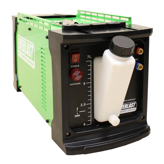
Page 14: Component Id And Explanation
Power Switch The cooler power switch may be left in the on position if it is connected to an Everlast welding product if the unit is to be used on and off during a production cycle. This will allow the main power switch on the welder to control the power. If storing, or if not in use overnight, switch the cooler off with the power switch. -
Page 15: Partially Disassembled Side View Of Components (Exploded View)
Specifications and Components Side View of Disassembled Components Side Panel Top Handle Mating Block Top Panel End Panel Coolant Tank Power Cable Coolant IN Coolant OUT Radiator/Heat Exchanger Pump Sealed Industrial Motor Power Switch Flow Alarm Flow Alarm Sensor Relay... -
Page 16: Connecting The Tig Torch
These fittings will require adapters to connect to the quick couplings. These are available usually from the torch supplier, or some universal type are available from Everlast to convert your torch, but your original fittings will have to be removed first. -
Page 17: Securing The Welder And Cooler Together
Setup Guide SECURING THE COOLER AND THE WELDER TOGETHER This cooler is designed specifically for the new generation panel design. It is designed to make a seamless match to the up- per welder unit, completing the stylish new look of the welder/cooler package. The cooler and welder can be attached togeth- er semi-permanently through the exclusive new mating system. -
Page 18: Installing Locking Pads To Cart And Cooler
INSTALL LOCKING PADS TO CART AND COOLER In order to offer complete package, Everlast has designed the new PowerCart 330 to mate securely to the welder and cooler package. The locking pads are designed to hold the cart and cooler together. In turn the mounting system between the weld- er and cooler also offer a “locked together”... -
Page 19: Installing Securing Brackets To Welder And Cooler
Setup Guide INSTALL SECURING BRACKETS TO THE WELDER The cooler includes two small connector brackets that help secure the cooler to the welder for semi-permanent mounting. Locate the brackets and install the bracket to the bottom of the welder welder first using three m4 screws. For ease of installa- tion, lay the welder on its side to access the bottom plate of the welder. -
Page 20: Installing Welder To Cooler
Setup Guide INSTALL THE WELDER TO THE COOLER Install the welder to the cooler after installing the securing brackets to the welder (See previous page). Line up the welder and cooler so that the mating surfaces roughly match, making sure the bottom lip of the welder is slightly in front of the cool- er lip before they touch. -
Page 21: Trouble Shooting Flow Alarm Issues And No Run Issues
Trouble Shooting Flow Alarm Issues The flow alarm has been designed to both illuminate and sound an audible alarm when flow is less than optimal. The flow alarm can be activated for several reasons: • Twisted, kinked or melted torch water line. •...
Need help?
Do you have a question about the PowerCool 375 and is the answer not in the manual?
Questions and answers