Advertisement
Polar Heart Rate Receiver KickStart (#28048)
This component is not sold individually by Parallax. It is included in the Heart Rate Monitor
Experiment Kit (#28037).
What It Can Do
Receives heart beat signals from a compatible sensor transmitter
•
Indicates a received heartbeat signal using a LOW/HIGH output signal
•
Wirelessly interfaces to transmitter with a range of up to four feet
•
The Polar Heart Rate Receiver is designed to receive heart beat signals from compatible Polar
heart rate sensors. Together, the sensor and receiver provides a low-cost and convenient heart
rate monitoring system that can be connected to most any microcontroller. Example uses include
home exercise and sports training.
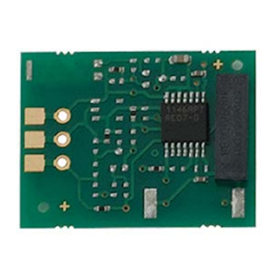
The Heart Rate Receiver is a stand-alone module, with on-board connections for power (3.3 V to
5 V), ground, and signal. It wirelessly interfaces to a compatible Polar coded or un-coded sensor
transmitter, such as the Polar T34 Non-Coded Transmitter.
Note: Range between transmitter and receiver is intentionally limited to about 3 to 4 feet, so that
multiple heart rate monitors can be used within the same general area.
Parts List
Polar Heart Rate Receiver
•
Polar T34 Non-Coded Heart Rate Transmitter
•
BASIC Stamp HomeWork Board, Propeller QuickStart, or Arduino Uno microcontroller
•
22 gauge solid conductor hookup wire
•
Copyright © Parallax Inc.
Web Site: www.parallax.com
Forums: forums.parallax.com
Sales: sales@parallax.com
Technical: support@parallax.com
Office: (916) 624-8333
Fax: (916) 624-8003
Sales: (888) 512-1024
Tech Support: (888) 997-8267
Page 1 of 6
Advertisement
Table of Contents

Summary of Contents for Parallax 28048
- Page 1 Technical: support@parallax.com Tech Support: (888) 997-8267 Polar Heart Rate Receiver KickStart (#28048) This component is not sold individually by Parallax. It is included in the Heart Rate Monitor Experiment Kit (#28037). What It Can Do Receives heart beat signals from a compatible sensor transmitter •...
- Page 2 Note: To make it easy to connect the Heart Rate Receiver to a breadboard or other circuit, solder a three-pin male header connector (Parallax #451-00303, not included) to the pads on the side of the module. As shown in the diagrams in this KickStart, the long portion of the header pins is on the side of the board with the foam tape.
- Page 3 IF sample AND oldSample <> sample THEN DEBUG "Beat", CR oldSample = sample 'Store last signal received LOOP Note: When this program is run, the BASIC Stamp Debug Terminal will automatically open. Copyright © Parallax Inc. Page 3 of 6...
- Page 4 'Pin definitions HR_RX 'Variable Definitions byte oldSample byte sample PUB go 'Start the Parallax Serial Terminal pst.start(115_200) pst.clear 'Set signal pin to input dira[HR_RX]~ pst.str(string("Waiting for heart beat...", pst#NL)) 'Wait until a heart beat is detected repeat until ina[HR_RX] Copyright © Parallax Inc.
- Page 5 := sample 'Store last signal received Note: This program uses the Parallax Serial Terminal object library, which is included with the Propeller Tool software download. Note: To view the results of the demonstration, after uploading is complete run the Parallax Serial Terminal from the Run menu, or press F12.
- Page 6 Note: To view the results of the demonstration, after uploading is complete click the Serial Monitor icon in the Arduino IDE. This displays the Serial Monitor window. Momentarily depress the Reset button on the Arduino board to restart the sketch. Copyright © Parallax Inc. Page 6 of 6...
Need help?
Do you have a question about the 28048 and is the answer not in the manual?
Questions and answers