Table of Contents
Advertisement
Quick Links
Advertisement
Table of Contents

Summary of Contents for ASTEL TSA 082
- Page 1 TSA 082 VIDEO ALARM SEQUENTIAL SWITCHER OPERATING INSTRUCTIONS v2.0...
-
Page 2: Table Of Contents
CONTENTS Safety precautions ............................2 Preface ..............................3 Features..............................3 Precautions...............................3 Controls and connectors...........................4 Connections..............................6 Alarm connection ............................7 VCR CLOCK connection ..........................7 Vertical interval switching .........................7 Alarm specification............................7 Remote control ............................7 Set-up ...............................8 Standard setting............................10 Self test..............................10 Installation...............................10 Appearance ............................11 Specifications............................11 Optional accessory ..........................12 SAFETY PRECAUTIONS In order to prevent any fatal accidents caused WARNING:... -
Page 3: Preface
Do Standard BNC-type input and output connectors turn power off immediately and refer servicing enables the TSA 082 to be used with other to qualified service personnel. • Avoid using this unit under the following CCTV switchers, cameras, monitors and video tape recorders. -
Page 4: Controls And Connectors
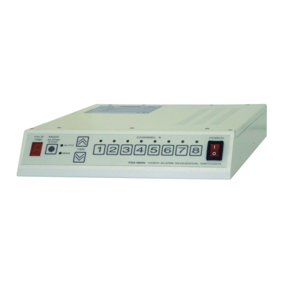
CONTROLS AND CONNECTORS FRONT PANEL (1) CH B - TIME (5) POWER LED display to show the sequence of the Switch to turn the power on / off - lights in the CHANNEL B or the sequential time of the power on position. - Page 5 REAR PANEL FUSE MODEL No. TSA 082 (1) FUSE T 315 mA (6) ALM Fuse socket. Alarm output connector (terminal block), open collector output. It is suitable to connect the video tape recorder with alarm input. (2) CH A BNC video output connector of the CHANNEL A.
-
Page 6: Connections
• Also refer to the instruction manual of the equipment to be connected. CAM 4 CAM 8 CAM 2 CAM 6 FUSE M ODEL No. TSA 082 CAM 1 CAM 5 ALARM SENSORS CAM 3 CAM 7 AC MAINS... -
Page 7: Alarm Connection
ALARM / REMOTE CONTROL CONNECTION Connection diagram: Notes: Notes: • Negative triggering - all alarm switches must • T1 - start/stop key be opened, in case of alarm they are closed. • T2 - manual scan key • Positive triggering - all alarm switches must be closed, in case of alarm they are opened. -
Page 8: Set-Up
SET-UP Set-up is made by the help of the LED display located on the front panel of the unit. Numerical codes are used to locate the selected setting. All settings are as follows: 1 - CHANNEL B mode (normal, VCR-CLOCK, frame-by-frame) 2 - CHANNEL B sequential time (1 - 90 sec.) 3 - CHANNEL B number of inputs (1 - 8) 4 - CHANNEL B frame number (1 - 99 frames) - Page 9 Set the number of frames by pressing up/down selectors. Press "•", select the next setting: "5" (ALARM activity) Select "0." for "off" and "1." for CHANNEL A or "2." for CHANNEL B. Press "•", select the next setting: "6" (ALARM seq. time) Adjust sequential time by pressing up/down selectors.
-
Page 10: Standard Setting
STANDARD SETTING SELF TEST Switch off the unit. Press the key "1" and turn Switch off the unit. Press the key "4" and turn the power on. All settings are as follows: the power on. All video inputs are sequentially switched both output... -
Page 11: Appearance
APPEARANCE One unit Two units SPECIFICATIONS Video inputs 1 Vpp / 75 Ω, BNC Video outputs 1 Vpp / 75 Ω, BNC 10 MHz ± 3 dB Video bandwidth > 60 dB Signal / noise ratio Crosstalk 56 dB (4.5 MHz) Switching interval adjustable, 1 to 90 sec. -
Page 12: Optional Accessory
PIN ASSIGNMENT Alarm input / remote control connector D-9F: PIN No. ALARM REMOTE ALARM 1 ALARM 2 ALARM 3 n.c. ALARM 4 n.c. ALARM 5 n.c. ALARM 6 n.c. ALARM 7 n.c. ALARM 8 n.c. Alarm output / VCR Clock connector: ALARM OUT VCR CLOCK OPTIONAL ACCESSORY... - Page 16 ASTEL d.o.o., Dutovlje 138, 6221 Dutovlje, Slovenia Tel: +386 5 7310771, +386 5 7310772 Fax:+386 5 7310789 E-mail: sales@astel-cctv.com Web: www.astel-cctv.com...
Need help?
Do you have a question about the TSA 082 and is the answer not in the manual?
Questions and answers